Mobrey
Mobrey
Mobrey

You also want an ePaper? Increase the reach of your titles
YUMPU automatically turns print PDFs into web optimized ePapers that Google loves.
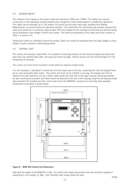
4.4 SENSOR CABLESThe ultrasonic drive signals on the sensor cables are normally at 1MHz and 3.3MHz. The cables are a specialconstruction of two separately screened twisted pairs, designed to meet electromagnetic compatibility regulations.The cables can be extended up to 100 metres, but should use the same cable type, available from <strong>Mobrey</strong>Measurement. (or consult factory for alternative vendors). The certification for intrinsically safe systems requires thatcable joins should be in enclosures rated at least IP20 and suitable for the intended enviornment and that the wiringshould withstand a test voltage of 500V rms to earth. The electrical parameters of the cable used must conform toTable 1 in section 2.4.Twisting the cables on installation should be avoided. Cable runs should be separated from any high voltage or mainscables, to avoid crosstalk or switching transients.4.5 CONTROL UNITThe control unit housing is rated IP65. It is suitable for mounting outside, but this should be above any flood level,away from any overflow water path, and away from direct sunlight. Internal sensors turn the LCD backlight off if thetemperature is excessive.The control unit must not be mounted in areas where an explosion hazard exists.It is not necessary or advisable to remove the lid to the upper part of the box, containing the LCD and keypad.Thereare no user serviceable parts inside. The control unit must not be modifed in any way. The keypad and LCD arelinked to the lower electronic pcb by a ribbon cable at the left hand side of the upper housing. Mounting bracketsfor wall mounting are provided, and these should be attached to the rear of the housing using the self tapping screws(also provided).The brackets are then used to wall mount the MSM400, using the six mounting holes available.Dimensional information is shown below:203.5Internal wall mounting holes33.35 80.0224.2236.7100.0104.212.54.26 off mounting holes Ø5.0226.5241.5256.5Figure 8 : MSM 400 Control Unit DimensionsNote that the weight of the MSM400 is 2Kg. To conform with safety requirements the wall should be capable ofsupporting 4 x this weight, ie. 8Kg. 5mm diameter steel screws should be used.IP25812