Mobrey
Mobrey
Mobrey

Create successful ePaper yourself
Turn your PDF publications into a flip-book with our unique Google optimized e-Paper software.
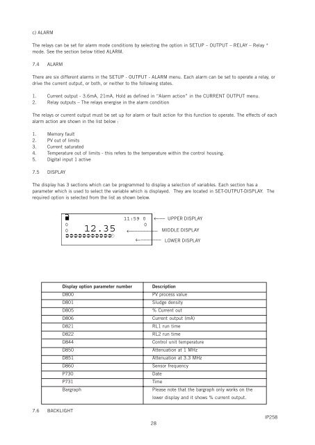
c) ALARMThe relays can be set for alarm mode conditions by selecting the option in SETUP – OUTPUT – RELAY – Relay *mode. See the section below titled ALARM.7.4 ALARMThere are six different alarms in the SETUP - OUTPUT - ALARM menu. Each alarm can be set to operate a relay, ordrive the current output, or both, or neither to the following states.1. Current output - 3.6mA, 21mA, Hold as defined in “Alarm action” in the CURRENT OUTPUT menu.2. Relay outputs – The relays energise in the alarm conditionThe relays or current output must be set up for alarm or fault action for this function to operate. The effects of eachalarm action are shown in the list below :1. Memory fault2. PV out of limits3. Current saturated4. Temperature out of limits - this refers to the temperature within the control housing.5. Digital input 1 active7.5 DISPLAYThe display has 3 sections which can be programmed to display a selection of variables. Each section has aparameter which is used to select the variable which is displayed. They are located in SET-OUTPUT-DISPLAY. Therequired option is selected from the list as shown below.■ 11:59 0 ←−− UPPER DISPLAY0 00 12.35 ←−−−−−−−−− MIDDLE DISPLAY←−−−−−−− LOWER DISPLAYDisplay option parameter numberD800D801D805D806D821D822D844D850D851D860P730P731BargraphDescriptionPV process valueSludge density% Current outCurrent output (mA)RL1 run timeRL2 run timeControl unit temperatureAttenuation at 1 MHzAttenuation at 3.3 MHzSensor frequencyDateTimePlease note that the bargraph only works on thelower display and it shows % current output.7.6 BACKLIGHT28IP258