Mobrey
Mobrey
Mobrey

Create successful ePaper yourself
Turn your PDF publications into a flip-book with our unique Google optimized e-Paper software.
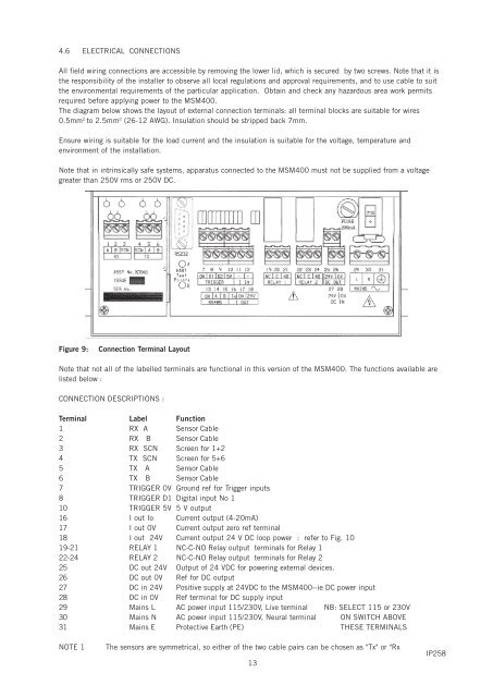
4.6 ELECTRICAL CONNECTIONSAll field wiring connections are accessible by removing the lower lid, which is secured by two screws. Note that it isthe responsibility of the installer to observe all local regulations and approval requirements, and to use cable to suitthe environmental requirements of the particular application. Obtain and check any hazardous area work permitsrequired before applying power to the MSM400.The diagram below shows the layout of external connection terminals: all terminal blocks are suitable for wires0.5mm 2 to 2.5mm 2 (26-12 AWG). Insulation should be stripped back 7mm.Ensure wiring is suitable for the load current and the insulation is suitable for the voltage, temperature andenvironment of the installation.Note that in intrinsically safe systems, apparatus connected to the MSM400 must not be supplied from a voltagegreater than 250V rms or 250V DC.FUSE200mAK7941Figure 9:Connection Terminal LayoutNote that not all of the labelled terminals are functional in this version of the MSM400. The functions available arelisted below :CONNECTION DESCRIPTIONS :Terminal Label Function1 RX A Sensor Cable2 RX B Sensor Cable3 RX SCN Screen for 1+24 TX SCN Screen for 5+65 TX A Sensor Cable6 TX B Sensor Cable7 TRIGGER 0V Ground ref for Trigger inputs8 TRIGGER D1 Digital input No 110 TRIGGER 5V 5 V output16 I out Io Current output (4-20mA)17 I out 0V Current output zero ref terminal18 I out 24V Current output 24 V DC loop power : refer to Fig. 1019-21 RELAY 1 NC-C-NO Relay output terminals for Relay 122-24 RELAY 2 NC-C-NO Relay output terminals for Relay 225 DC out 24V Output of 24 VDC for powering external devices.26 DC out 0V Ref for DC output27 DC in 24V Positive supply at 24VDC to the MSM400--ie DC power input28 DC in 0V Ref terminal for DC supply input29 Mains L AC power input 115/230V, Live terminal NB: SELECT 115 or 230V30 Mains N AC power input 115/230V, Neural terminal ON SWITCH ABOVE31 Mains E Protective Earth (PE) THESE TERMINALSNOTE 1The sensors are symmetrical, so either of the two cable pairs can be chosen as "Tx" or "Rx13IP258