Mobrey
Mobrey
Mobrey

Create successful ePaper yourself
Turn your PDF publications into a flip-book with our unique Google optimized e-Paper software.
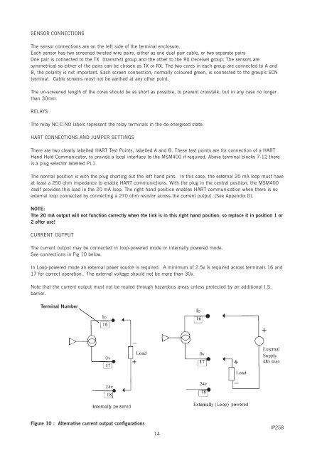
SENSOR CONNECTIONSThe sensor connections are on the left side of the terminal enclosure.Each sensor has two screened twisted wire pairs, either as one dual pair cable, or two separate pairsOne pair is connected to the TX (transmit) group and the other to the RX (receive) group. The sensors aresymmetrical so either of the pairs can be chosen as TX or RX. The two cores in each group are connected to A andB, the polarity is not important. Each screen connection, normally coloured green, is connected to the group’s SCNterminal. Cable screens must not be earthed at any other point.The un-screened length of the cores should be as short as possible, to prevent crosstalk, but in any case no longerthan 30mm.RELAYSThe relay NC-C-NO labels represent the relay terminals in the de-energised state.HART CONNECTIONS AND JUMPER SETTINGSThere are two clearly labelled HART Test Points, labelled A and B. These test points are for connection of a HARTHand Held Communicator, to provide a local interface to the MSM400 if required. Above terminal blocks 7-12 thereis a plug selector labelled PL1.The normal position is with the plug shorting out the left hand pins. In this case, the external 20 mA loop must haveat least a 250 ohm impedance to enable HART communictions. With the plug in the central position, the MSM400itself provides this load in the 20 mA loop. The right hand position enables HART communication when there is noexternal loop connected by connecting a 270 ohm resistor across the current output. (See Appendix D).NOTE:The 20 mA output will not function correctly when the link is in this right hand position, so replace it in position 1 or2 after use!CURRENT OUTPUTThe current output may be connected in loop-powered mode or internally powered mode.See connections in Fig 10 below.In Loop-powered mode an external power source is required. A minimum of 2.5v is required across terminals 16 and17 for correct operation. The external voltage should not be more than 30v.Note that the current output must not be routed through hazardous areas unless protected by an additional I.S.barrier.Terminal NumberFigure 10 : Alternative current output configurations14IP258