IRAC Instrument Handbook - IRSA - California Institute of Technology
IRAC Instrument Handbook - IRSA - California Institute of Technology
IRAC Instrument Handbook - IRSA - California Institute of Technology

You also want an ePaper? Increase the reach of your titles
YUMPU automatically turns print PDFs into web optimized ePapers that Google loves.
7.3.2 Optical Banding and Internal Scattering<br />
<strong>IRAC</strong> <strong>Instrument</strong> <strong>Handbook</strong><br />
The banding effect manifests itself as the rows and columns that contain a bright source having an<br />
enhanced level <strong>of</strong> brightness. This happens only in the Si:As arrays and has been shown to be due to<br />
internal optical scattering (inside the array). Both bright stellar sources and bright extended sources cause<br />
banding. It is clearly different from the optical diffraction patterns and the column pull-down effect. The<br />
SSC pipeline corrects for banding, but it does not model the flaring <strong>of</strong> banding towards the edges <strong>of</strong> the<br />
array. Therefore, the pipeline correction is not always perfect.<br />
Banding only appears in <strong>IRAC</strong> channels 3 and 4 (5.8 and 8 micron bands), and it is stronger in channel 3.<br />
Banding probably occurs at all intensity levels, but only appears obvious around bright sources that are at<br />
or near saturation levels. Banding is seen both in row and column directions, though their relative<br />
intensities are somewhat different. In addition, there is an electronic effect. Channel 4 has a strong row<br />
pull-up, and channel 3 has a weak column pull-up. The column pull-up is uniform across the row where<br />
the source is bright. The optical banding intensity falls <strong>of</strong>f with distance from the bright spot. Cosmic ray<br />
hits cause electronic banding, but not optical banding.<br />
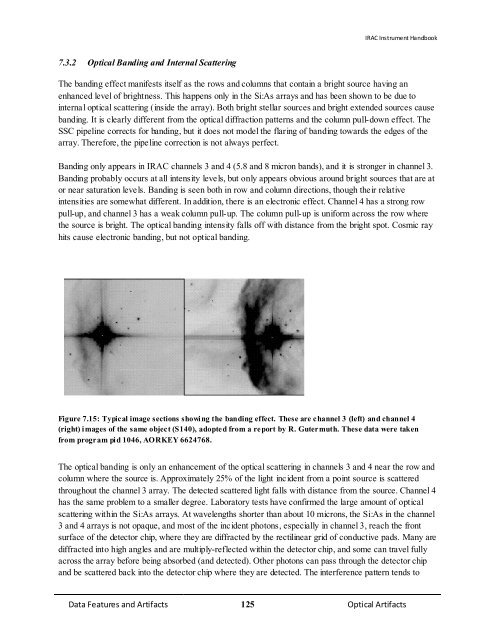
Figure 7.15: Typical image sections showing the banding effect. These are channel 3 (left) and channel 4<br />
(right) images <strong>of</strong> the same object (S140), adopted from a report by R. Gutermuth. These data were taken<br />
from program pid 1046, AORKEY 6624768.<br />
The optical banding is only an enhancement <strong>of</strong> the optical scattering in channels 3 and 4 near the row and<br />
column where the source is. Approximately 25% <strong>of</strong> the light incident from a point source is scattered<br />
throughout the channel 3 array. The detected scattered light falls with distance from the source. Channel 4<br />
has the same problem to a smaller degree. Laboratory tests have confirmed the large amount <strong>of</strong> optical<br />
scattering within the Si:As arrays. At wavelengths shorter than about 10 microns, the Si:As in the channel<br />
3 and 4 arrays is not opaque, and most <strong>of</strong> the incident photons, especially in channel 3, reach the front<br />
surface <strong>of</strong> the detector chip, where they are diffracted by the rectilinear grid <strong>of</strong> conductive pads. Many are<br />
diffracted into high angles and are multiply-reflected within the detector chip, and some can travel fully<br />
across the array before being absorbed (and detected). Other photons can pass through the detector chip<br />
and be scattered back into the detector chip where they are detected. The interference pattern tends to<br />
Data Features and Artifacts 125 Optical Artifacts