IRAC Instrument Handbook - IRSA - California Institute of Technology
IRAC Instrument Handbook - IRSA - California Institute of Technology
IRAC Instrument Handbook - IRSA - California Institute of Technology
You also want an ePaper? Increase the reach of your titles
YUMPU automatically turns print PDFs into web optimized ePapers that Google loves.
<strong>IRAC</strong> <strong>Instrument</strong> <strong>Handbook</strong><br />
This is mostly noticeable in very low background conditions. This is corrected by adding to the individual<br />
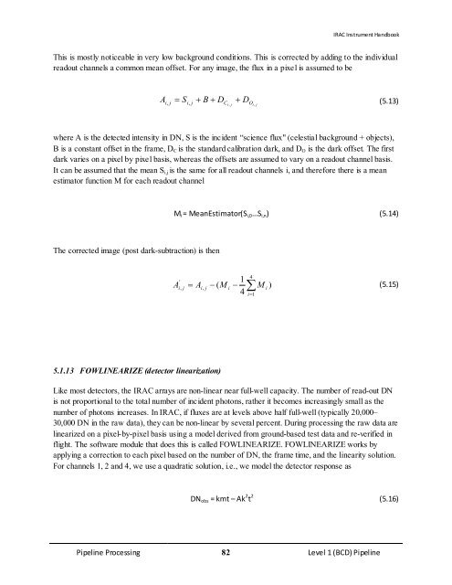
readout channels a common mean <strong>of</strong>fset. For any image, the flux in a pixel is assumed to be<br />
A i,<br />
j Si<br />
, j + B + DC<br />
+ D<br />
i , j Oi<br />
, j<br />
= (5.13)<br />
where A is the detected intensity in DN, S is the incident “science flux" (celestial background + objects),<br />
B is a constant <strong>of</strong>fset in the frame, DC is the standard calibration dark, and DO is the dark <strong>of</strong>fset. The first<br />
dark varies on a pixel by pixel basis, whereas the <strong>of</strong>fsets are assumed to vary on a readout channel basis.<br />
It can be assumed that the mean Si,j is the same for all readout channels i, and therefore there is a mean<br />
estimator function M for each readout channel<br />
The corrected image (post dark-subtraction) is then<br />
Mi = MeanEstimator(Si,0…Si,n) (5.14)<br />
4<br />
'<br />
1<br />
A i j = Ai,<br />
j − ( M i − M i )<br />
(5.15)<br />
4<br />
, ∑<br />
i=<br />
1<br />
5.1.13 FOWLINEARIZE (detector linearization)<br />
Like most detectors, the <strong>IRAC</strong> arrays are non-linear near full-well capacity. The number <strong>of</strong> read-out DN<br />
is not proportional to the total number <strong>of</strong> incident photons, rather it becomes increasingly small as the<br />
number <strong>of</strong> photons increases. In <strong>IRAC</strong>, if fluxes are at levels above half full-well (typically 20,000–<br />
30,000 DN in the raw data), they can be non-linear by several percent. During processing the raw data are<br />
linearized on a pixel-by-pixel basis using a model derived from ground-based test data and re-verified in<br />
flight. The s<strong>of</strong>tware module that does this is called FOWLINEARIZE. FOWLINEARIZE works by<br />
applying a correction to each pixel based on the number <strong>of</strong> DN, the frame time, and the linearity solution.<br />
For channels 1, 2 and 4, we use a quadratic solution, i.e., we model the detector response as<br />
DNobs = kmt – Ak 2 t 2 (5.16)<br />
Pipeline Processing 82 Level 1 (BCD) Pipeline


