IRAC Instrument Handbook - IRSA - California Institute of Technology
IRAC Instrument Handbook - IRSA - California Institute of Technology
IRAC Instrument Handbook - IRSA - California Institute of Technology

You also want an ePaper? Increase the reach of your titles
YUMPU automatically turns print PDFs into web optimized ePapers that Google loves.
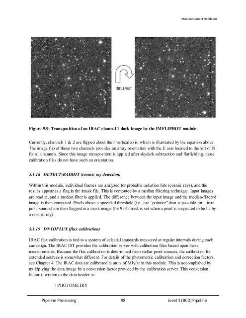
Figure 5.9: Transposition <strong>of</strong> an <strong>IRAC</strong> channel 1 dark image by the IMFLIPROT module.<br />
<strong>IRAC</strong> <strong>Instrument</strong> <strong>Handbook</strong><br />
Currently, channels 1 & 2 are flipped about their vertical axis, which is illustrated by the equation above.<br />
The image flip <strong>of</strong> these two channels provides an array orientation with the E axis located to the left <strong>of</strong> N<br />
for all channels. Since this image transposition is applied after skydark subtraction and flatfielding, those<br />
calibration files do not have such an orientation.<br />
5.1.18 DETECT-RADHIT (cosmic ray detection)<br />
Within this module, individual frames are analyzed for probable radiation hits (cosmic rays), and the<br />
results appear as a flag in the imask file. This is computed by a median filtering technique. Input images<br />
are read in, and a median filter is applied. The difference between the input image and the median-filtered<br />
image is then computed. Pixels above a specified threshold (i.e., are “pointier" than is possible for a true<br />
point source) are then flagged in a mask image (bit 9 <strong>of</strong> imask is set when a pixel is suspected to be hit by<br />
a cosmic ray).<br />
5.1.19 DNTOFLUX (flux calibration)<br />
<strong>IRAC</strong> flux calibration is tied to a system <strong>of</strong> celestial standards measured at regular intervals during each<br />
campaign. The <strong>IRAC</strong> IST provides the calibration server with calibration files based upon these<br />
measurements. Because the flux calibration is determined from stellar point sources, the calibration for<br />
extended sources is somewhat different. For details <strong>of</strong> the photometric calibration and correction factors,<br />
see Chapter 4. The <strong>IRAC</strong> data are calibrated in units <strong>of</strong> MJy/sr in this module. This is accomplished by<br />
multiplying the data image by a conversion factor provided by the calibration server. This conversion<br />
factor is written to the data header as:<br />
/ PHOTOMETRY<br />
Pipeline Processing 85 Level 1 (BCD) Pipeline