D CDA3000 Inverter Drive System 750 W - 132 kW - Igor Chudov
D CDA3000 Inverter Drive System 750 W - 132 kW - Igor Chudov
D CDA3000 Inverter Drive System 750 W - 132 kW - Igor Chudov

Create successful ePaper yourself
Turn your PDF publications into a flip-book with our unique Google optimized e-Paper software.
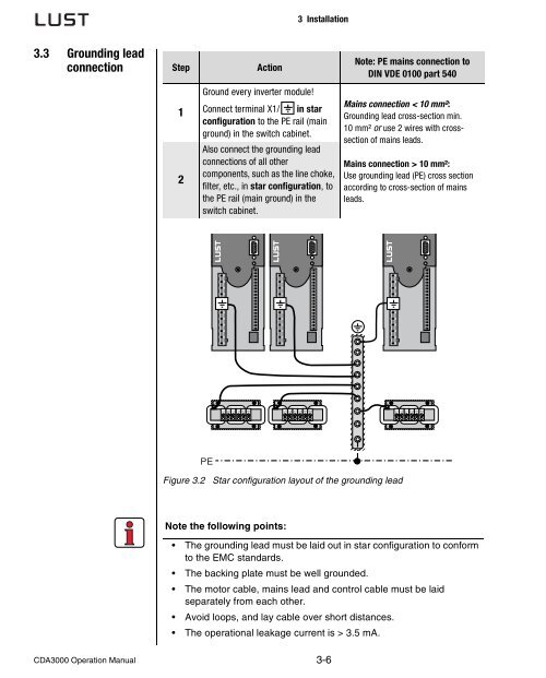
3.3 Grounding lead<br />
connection<br />
<strong>CDA3000</strong> Operation Manual<br />
Step Action<br />
1<br />
2<br />
3 Installation<br />
Ground every inverter module!<br />
Connect terminal X1/ in star<br />
configuration to the PE rail (main<br />
ground) in the switch cabinet.<br />
Also connect the grounding lead<br />
connections of all other<br />
components, such as the line choke,<br />
filter, etc., in star configuration, to<br />
the PE rail (main ground) in the<br />
switch cabinet.<br />
PE<br />
Figure 3.2 Star configuration layout of the grounding lead<br />
Note the following points:<br />
;; ;<br />
U1 U2 V1 V2 W1 W2<br />
3-6<br />
Note: PE mains connection to<br />
DIN VDE 0100 part 540<br />
Mains connection < 10 mm²:<br />
Grounding lead cross-section min.<br />
10 mm² or use 2 wires with crosssection<br />
of mains leads.<br />
Mains connection > 10 mm²:<br />
Use grounding lead (PE) cross section<br />
according to cross-section of mains<br />
leads.<br />
U1 U2 V1 V2 W1 W2<br />
The grounding lead must be laid out in star configuration to conform<br />
to the EMC standards.<br />
The backing plate must be well grounded.<br />
The motor cable, mains lead and control cable must be laid<br />
separately from each other.<br />
Avoid loops, and lay cable over short distances.<br />
The operational leakage current is > 3.5 mA.<br />
;<br />
;;<br />
;;<br />
U1 U2 V1 V2 W1 W2<br />
;;<br />
;;<br />
;;