D CDA3000 Inverter Drive System 750 W - 132 kW - Igor Chudov
D CDA3000 Inverter Drive System 750 W - 132 kW - Igor Chudov
D CDA3000 Inverter Drive System 750 W - 132 kW - Igor Chudov

Create successful ePaper yourself
Turn your PDF publications into a flip-book with our unique Google optimized e-Paper software.
3.7 Braking resistor<br />
(RB)<br />
<strong>CDA3000</strong> Operation Manual<br />
3 Installation<br />
In regenerative operation, e.g. braking the drive, the motor feeds energy<br />
back into the inverter. This increases the voltage in the DC-link. If the<br />
voltage exceeds a threshold value, the internal braking transistor is<br />
activated and the regenerated power is converted into heat by way of a<br />
braking resistor.<br />
The switching transistor is installed as standard. The design of the<br />
external braking resistor depends on a number of drive factors:<br />
for example the load to be moved, the required dynamics of the drive or<br />
the braking and cycle duration.<br />
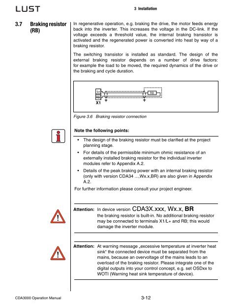
L+<br />
RB<br />
X1<br />
Figure 3.6 Braking resistor connection<br />
Note the following points:<br />
The design of the braking resistor must be clarified at the project<br />
planning stage.<br />
For details of the permissible minimum ohmic resistance of an<br />
externally installed braking resistor for the individual inverter<br />
modules refer to Appendix A.2.<br />
Details of the peak braking power with an internal braking resistor<br />
(only with version CDA34 ...,Wx.x,BR) are also given in Appendix<br />
A.2.<br />
For further information please consult your project engineer.<br />
Attention: In device version CDA3X.xxx, Wx.x, BR<br />
the braking resistor is built-in. No additional braking resistor<br />
may be connected to terminals X1/L+ and RB; this would<br />
damage the inverter module.<br />
Attention: At warning message „excessive temperature at inverter heat<br />
sink“ the connected device must be separated from the<br />
mains, because an overvoltage of the mains leads to an<br />
overload of the braking resistor. Please integrate one of the<br />
digital outputs into your control concept, e.g. set OSDxx to<br />
WOTI (Warning heat sink temperature of device).<br />
3-12<br />
RB