Fuxx Control - ARS 2320 / ARS 2340 Instruction Manual - Kuhnke
Fuxx Control - ARS 2320 / ARS 2340 Instruction Manual - Kuhnke
Fuxx Control - ARS 2320 / ARS 2340 Instruction Manual - Kuhnke

You also want an ePaper? Increase the reach of your titles
YUMPU automatically turns print PDFs into web optimized ePapers that Google loves.
KUHNKE Automation <strong>Fuxx</strong> <strong>Control</strong> <strong>ARS</strong> <strong>2320</strong> / <strong>ARS</strong> <strong>2340</strong><br />
Positioning and interpolation<br />
Trajectory calculation:<br />
- Position setpoint<br />
- Speed feedforward<br />
- Current feedforward<br />
Setpoint management<br />
- Analog inputs<br />
- Fixed values<br />
- Synchronisation<br />
- Ramp generator<br />
X2A<br />
X2B<br />
X10<br />
Position<br />
controller<br />
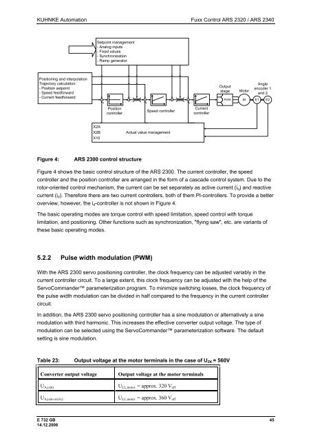
Figure 4: <strong>ARS</strong> 2300 control structure<br />
Speed controller<br />
Actual value management<br />
Current<br />
controller<br />
Output<br />
stage Motor<br />
Angle<br />
encoder 1<br />
and 2<br />
PWM M E1 E2<br />
Figure 4 shows the basic control structure of the <strong>ARS</strong> 2300. The current controller, the speed<br />
controller and the position controller are arranged in the form of a cascade control system. Due to the<br />
rotor-oriented control mechanism, the current can be set separately as active current (iq) and reactive<br />
current (id). Therefore there are two current controllers, both of them PI-controllers. To provide a better<br />
overview, however, the id-controller is not shown in Figure 4.<br />
The basic operating modes are torque control with speed limitation, speed control with torque<br />
limitation, and positioning. Other functions such as synchronization, "flying saw", etc. are variants of<br />
these basic operating modes.<br />
5.2.2 Pulse width modulation (PWM)<br />
With the <strong>ARS</strong> 2300 servo positioning controller, the clock frequency can be adjusted variably in the<br />
current controller circuit. To a large extent, this clock frequency can be adjusted with the help of the<br />
ServoCommander parameterization program. To minimize switching losses, the clock frequency of<br />
the pulse width modulation can be divided in half compared to the frequency in the current controller<br />
circuit.<br />
In addition, the <strong>ARS</strong> 2300 servo positioning controller has a sine modulation or alternatively a sine<br />
modulation with third harmonic. This increases the effective converter output voltage. The type of<br />
modulation can be selected using the ServoCommander parameterization software. The default<br />
setting is sine modulation.<br />
Table 23: Output voltage at the motor terminals in the case of UZK = 560V<br />
Converter output voltage Output voltage at the motor terminals<br />
UA,(sin)<br />
UA,(sin+sin3x)<br />
ULL,motor = approx. 320 Veff<br />
ULL,motor = approx. 360 Veff<br />
E 732 GB 45<br />
14.12.2006