Fuxx Control - ARS 2320 / ARS 2340 Instruction Manual - Kuhnke
Fuxx Control - ARS 2320 / ARS 2340 Instruction Manual - Kuhnke
Fuxx Control - ARS 2320 / ARS 2340 Instruction Manual - Kuhnke

Create successful ePaper yourself
Turn your PDF publications into a flip-book with our unique Google optimized e-Paper software.
<strong>Fuxx</strong> <strong>Control</strong> <strong>ARS</strong> <strong>2320</strong> / <strong>ARS</strong> <strong>2340</strong> KUHNKE Automation<br />
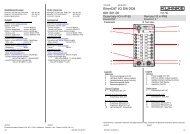
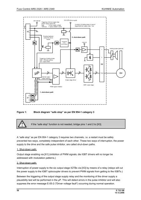
X3<br />
X1<br />
1<br />
2<br />
3<br />
4<br />
5<br />
6<br />
21<br />
9<br />
24V internal<br />
µP<br />
<strong>Control</strong>ler enabling DIN5<br />
Output stage enabling DIN4<br />
Triggering of driver supply relay<br />
(driver supply switch off)<br />
High = driver supply voltage<br />
"ON"Low = "pulse inhibitor" active<br />
Floating feedback<br />
contact for driver<br />
supply<br />
Triggering of holding brake<br />
High = lift brake (active)<br />
Low = apply brake<br />
Internal output<br />
stage enabling<br />
1. shut-down path<br />
15V IGTB driver supply<br />
monitoring<br />
of the<br />
driver supply<br />
"Locking" of holding brake in case of<br />
triggeringDriver supply relay = low<br />
6 6 6 3<br />
PWM signal inhibition<br />
Output stage driver<br />
2. shut-down path<br />
IGBT output stage<br />
Holding brake (optional)<br />
58 E 732 GB<br />
14.12.2006<br />
+24V-IO<br />
Figure 1: Block diagram “safe stop” as per EN 954-1 category 3<br />
If the “safe stop” function is not needed, bridge pins 1 and 2 to [X3].<br />
A “safe stop” as per EN 954-1 category 3 requires two channels, i.e. a restart must be safely<br />
prevented two ways, completely independent of each other. These two ways of interruption, the power<br />
supply to the drive and the safe pulse inhibitor, are called shut-down paths.<br />
1. Shut-down path:<br />
Output stage enabling via [X1] (inhibition of PWM signals; die IGBT drivers will no longer be<br />
addressed with modulation patterns.)<br />
2. Shut-down path:<br />
Interruption of power supply to the six output stage IGTBs via [X3] by means of a relay (relays will cut<br />
the power supply to the IGBT optocoupler drivers to prevent PWM signals from getting to the IGBTs.)<br />
Between the triggering of the output stage supply relay and the monitoring of the driver supply a<br />
plausibility test will be performed in the µP. This will detect errors in the pulse inhibitor and will also<br />
suppress the error message E-05-2 ("Driver voltage fault") occurring during normal operation.<br />
1<br />
2<br />
X6<br />
7,8,9<br />
SM