- Seite 1 und 2:
Leitfaden zu STN-Patentdatenbanken
- Seite 3 und 4:
Einleitung Leitfaden zu STN-Patentd
- Seite 5 und 6:
Leitfaden zu STN-Patentdatenbanken
- Seite 7 und 8:
Leitfaden zu STN-Patentdatenbanken
- Seite 9 und 10:
Leitfaden zu STN-Patentdatenbanken
- Seite 11 und 12:
Leitfaden zu STN-Patentdatenbanken
- Seite 13 und 14:
Einführung 13
- Seite 15 und 16:
1.2 Durchführung der Recherche Off
- Seite 17 und 18:
Rechercheart Erläuterung Einführu
- Seite 19 und 20:
Einführung 3.2 Bibliographische Pa
- Seite 21 und 22:
3.4 Volltextdatenbanken (national)
- Seite 23 und 24: Einführung 3.6 Fachspezifische Pat
- Seite 25 und 26: Inhalt der Patentdatenbanken 25
- Seite 27 und 28: 4.3.1 Mehrere Dokumente Inhalt der
- Seite 29 und 30: Inhalt der Patentdatenbanken 5 Chem
- Seite 31 und 32: 5.5 Aktualität Inhalt der Patentda
- Seite 33 und 34: Inhalt der Patentdatenbanken LSUS R
- Seite 35 und 36: Inhalt der Patentdatenbanken 6 Derw
- Seite 37 und 38: 6.6 Ausgewählte Felder Inhalt der
- Seite 39 und 40: Inhalt der Patentdatenbanken ES Spa
- Seite 41 und 42: Inhalt der Patentdatenbanken 8 Derw
- Seite 43 und 44: Originaltextdaten: Inhalt der Paten
- Seite 45 und 46: Inhalt der Patentdatenbanken Metall
- Seite 47 und 48: Inhalt der Patentdatenbanken the fi
- Seite 49 und 50: Inhalt der Patentdatenbanken A47J00
- Seite 51 und 52: Inhalt der Patentdatenbanken 8.7.2
- Seite 53 und 54: 9.4 Dokument aus ENCOMPPAT(2) Anzei
- Seite 55 und 56: Inhalt der Patentdatenbanken Intern
- Seite 57 und 58: Antrieb ausgeruestet sind. ... Inha
- Seite 59 und 60: Inhalt der Patentdatenbanken 200807
- Seite 61 und 62: Inhalt der Patentdatenbanken EPFULL
- Seite 63 und 64: Angaben zu Zitierungen, Relationen
- Seite 65 und 66: 11.7 Ausgewählte Felder Inhalt der
- Seite 67 und 68: 12.4 Fortschreibung Inhalt der Pate
- Seite 69 und 70: Inhalt der Patentdatenbanken AN 292
- Seite 71 und 72: 13 GBFULL 13.1 Typische Anfragen In
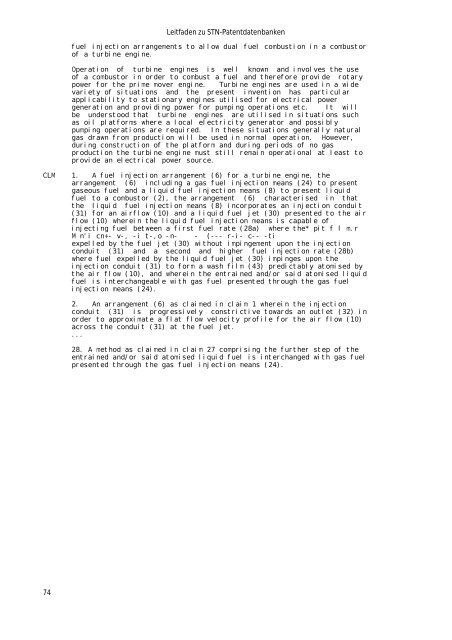
- Seite 73: Inhalt der Patentdatenbanken to a c
- Seite 77 und 78: Inhalt der Patentdatenbanken 14.6 D
- Seite 79 und 80: 14.7 Ausgewählte Felder Inhalt der
- Seite 81 und 82: Inhalt der Patentdatenbanken Angabe
- Seite 83 und 84: Inhalt der Patentdatenbanken NCLS:
- Seite 85 und 86: Inhalt der Patentdatenbanken writin
- Seite 87 und 88: 16 IMSPATENTS 16.1 Typische Anfrage
- Seite 89 und 90: Inhalt der Patentdatenbanken Die ge
- Seite 91 und 92: 16.6 Ausgewählte Felder Inhalt der
- Seite 93 und 94: 17.3 Inhalt Inhalt der Patentdatenb
- Seite 95 und 96: PI; PIT; PRAI; REP; TI Inhalt der P
- Seite 97 und 98: Inhalt der Patentdatenbanken DELAVA
- Seite 99 und 100: Formate mit vollem Preis: Inhalt de
- Seite 101 und 102: Inhalt der Patentdatenbanken ist da
- Seite 103 und 104: 18 JAPIO 18.1 Typische Anfragen Inh
- Seite 105 und 106: 18.6.2 INPADOC-Daten Anzeigeformat:
- Seite 107 und 108: 19.6 Dokument aus KOREAPAT Anzeigef
- Seite 109 und 110: 20 LITALERT 20.1 Kurzbeschreibung I
- Seite 111 und 112: 21 PATDD 21.1 Typische Anfragen Inh
- Seite 113 und 114: -----+-----------------------------
- Seite 115 und 116: 22 PATDPA 22.1 Typische Anfragen In
- Seite 117 und 118: Abstract, Hauptanspruch: Inhalt der
- Seite 119 und 120: Inhalt der Patentdatenbanken PI DE
- Seite 121 und 122: 22.7 Ausgewählte Felder Inhalt der
- Seite 123 und 124: Inhalt der Patentdatenbanken Zusät
- Seite 125 und 126:
Inhalt der Patentdatenbanken AB (Zu
- Seite 127 und 128:
23.7 Ausgewählte Felder Inhalt der
- Seite 129 und 130:
24.6 Dokumente aus PATDPASPC Anzeig
- Seite 131 und 132:
25 PATIPC 25.1 Typische Anfragen In
- Seite 133 und 134:
26 PCTFULL 26.1 Typische Anfragen I
- Seite 135 und 136:
Inhalt der Patentdatenbanken ABEN T
- Seite 137 und 138:
26.7 Ausgewählte Felder Inhalt der
- Seite 139 und 140:
27.5 Dokument aus PCTGEN Anzeigefor
- Seite 141 und 142:
Inhalt der Patentdatenbanken RD-Dok
- Seite 143 und 144:
28.7 Ausgewählte Felder Inhalt der
- Seite 145 und 146:
29.5 Aktualität Inhalt der Patentd
- Seite 147 und 148:
30 USGENE 30.1 Kurzbeschreibung Inh
- Seite 149 und 150:
Inhalt der Patentdatenbanken 151 iq
- Seite 151 und 152:
Inhalt der Patentdatenbanken Abstra
- Seite 153 und 154:
Inhalt der Patentdatenbanken substr
- Seite 155 und 156:
31.8 Ausgewählte Felder IPC1 7: IC
- Seite 157 und 158:
32.6 Dokument aus USPATOLD Anzeigef
- Seite 159 und 160:
Recherchearten in Patentdatenbanken
- Seite 161 und 162:
34 Recherchen nach Freitext 34.1 Fe
- Seite 163 und 164:
Recherchearten in Patentdatenbanken
- Seite 165 und 166:
Recherchearten in Patentdatenbanken
- Seite 167 und 168:
Recherchearten in Patentdatenbanken
- Seite 169 und 170:
Recherchearten in Patentdatenbanken
- Seite 171 und 172:
Recherchearten in Patentdatenbanken
- Seite 173 und 174:
E8 333368 ABOL/FA E9 250452 ABOR/FA
- Seite 175 und 176:
Recherchearten in Patentdatenbanken
- Seite 177 und 178:
Recherchearten in Patentdatenbanken
- Seite 179 und 180:
Recherchearten in Patentdatenbanken
- Seite 181 und 182:
Recherchearten in Patentdatenbanken
- Seite 183 und 184:
Recherchearten in Patentdatenbanken
- Seite 185 und 186:
Recherchearten in Patentdatenbanken
- Seite 187 und 188:
Recherchearten in Patentdatenbanken
- Seite 189 und 190:
Recherchearten in Patentdatenbanken
- Seite 191 und 192:
Recherchearten in Patentdatenbanken
- Seite 193 und 194:
35.5.3 STN-Format Recherchearten in
- Seite 195 und 196:
Recherchearten in Patentdatenbanken
- Seite 197 und 198:
Recherchearten in Patentdatenbanken
- Seite 199 und 200:
Recherchearten in Patentdatenbanken
- Seite 201 und 202:
=> S METHANOL(L)MOA/RL => S METHANO
- Seite 203 und 204:
Recherchearten in Patentdatenbanken
- Seite 205 und 206:
Recherchearten in Patentdatenbanken
- Seite 207 und 208:
Recherchearten in Patentdatenbanken
- Seite 209 und 210:
Recherchearten in Patentdatenbanken
- Seite 211 und 212:
E14 4339 CODE GIPR-R/PACO E15 247 C
- Seite 213 und 214:
Recherchearten in Patentdatenbanken
- Seite 215 und 216:
Recherchearten in Patentdatenbanken
- Seite 217 und 218:
Recherchearten in Patentdatenbanken
- Seite 219 und 220:
Recherchearten in Patentdatenbanken
- Seite 221 und 222:
37.8.2 PATDPAFULL Recherchearten in
- Seite 223 und 224:
Recherchearten in Patentdatenbanken
- Seite 225 und 226:
=> S W IT/DS L17 256 W IT/DS => S R
- Seite 227 und 228:
Recherchearten in Patentdatenbanken
- Seite 229 und 230:
Recherchearten in Patentdatenbanken
- Seite 231 und 232:
=> S WO99-12345/PN L5 1 WO99-12345/
- Seite 233 und 234:
Recherchearten in Patentdatenbanken
- Seite 235 und 236:
Recherchearten in Patentdatenbanken
- Seite 237 und 238:
Recherchearten in Patentdatenbanken
- Seite 239 und 240:
Recherchearten in Patentdatenbanken
- Seite 241 und 242:
Recherchearten in Patentdatenbanken
- Seite 243 und 244:
Recherchearten in Patentdatenbanken
- Seite 245 und 246:
Recherchearten in Patentdatenbanken
- Seite 247 und 248:
39.4.1.2 Recherchearten in Patentda
- Seite 249 und 250:
Recherchearten in Patentdatenbanken
- Seite 251 und 252:
Recherchearten in Patentdatenbanken
- Seite 253 und 254:
39.5.4 DWPI Recherchearten in Paten
- Seite 255 und 256:
Recherchearten in Patentdatenbanken
- Seite 257 und 258:
Recherchearten in Patentdatenbanken
- Seite 259 und 260:
Recherchearten in Patentdatenbanken
- Seite 261 und 262:
Recherchearten in Patentdatenbanken
- Seite 263 und 264:
40 Rechtsstandsrecherchen Recherche
- Seite 265 und 266:
Recherchearten in Patentdatenbanken
- Seite 267 und 268:
Folgende Felder sind vorhanden: Rec
- Seite 269 und 270:
Recherchearten in Patentdatenbanken
- Seite 271 und 272:
Recherchearten in Patentdatenbanken
- Seite 273 und 274:
Recherchearten in Patentdatenbanken
- Seite 275 und 276:
Recherchearten in Patentdatenbanken
- Seite 277 und 278:
=> D UP LS Recherchearten in Patent
- Seite 279 und 280:
Recherchearten in Patentdatenbanken
- Seite 281 und 282:
41 Zitierungsrecherchen 41.1 Typisc
- Seite 283 und 284:
Recherchearten in Patentdatenbanken
- Seite 285 und 286:
Recherchearten in Patentdatenbanken
- Seite 287 und 288:
Recherchearten in Patentdatenbanken
- Seite 289 und 290:
Recherchearten in Patentdatenbanken
- Seite 291 und 292:
Recherchearten in Patentdatenbanken
- Seite 293 und 294:
E1 THROUGH E4 ASSIGNED => D SEL E1
- Seite 295 und 296:
43.4 RDISCLOSURE Recherchearten in
- Seite 297 und 298:
44.2 Volltextbereitstellung Recherc
- Seite 299 und 300:
Recherchearten in Patentdatenbanken
- Seite 301 und 302:
44.3.3 Verwaltung der Dokumentordne
- Seite 303 und 304:
=> SEL L1 1- IPC.F E1 THROUGH E439
- Seite 305 und 306:
122 47 47 17.22 2005 123 44 44 16.1
- Seite 307 und 308:
Recherchearten in Patentdatenbanken
- Seite 309 und 310:
Recherchearten in Patentdatenbanken
- Seite 311 und 312:
Recherchearten in Patentdatenbanken
- Seite 313 und 314:
45.6 Verwendung von STN Express STN
- Seite 315 und 316:
Recherchearten in Patentdatenbanken
- Seite 317 und 318:
Recherchearten in Patentdatenbanken
- Seite 319 und 320:
Recherchearten in Patentdatenbanken
- Seite 321 und 322:
45.8.3 ANALYZE PLUS Recherchearten
- Seite 323 und 324:
Recherchearten in Patentdatenbanken
- Seite 325 und 326:
Recherchearten in Patentdatenbanken
- Seite 327 und 328:
Recherchearten in Patentdatenbanken
- Seite 329 und 330:
45.10.4.1 IPC1 7 Recherchearten in
- Seite 331 und 332:
Recherchearten in Patentdatenbanken
- Seite 333 und 334:
45.12.3 Rangreihen Recherchearten i
- Seite 335 und 336:
Recherchearten in Patentdatenbanken
- Seite 337 und 338:
Recherchearten in Patentdatenbanken
- Seite 339 und 340:
Recherchearten in Patentdatenbanken
- Seite 341 und 342:
Recherchearten in Patentdatenbanken
- Seite 343 und 344:
Recherchearten in Patentdatenbanken
- Seite 345 und 346:
Recherchearten in Patentdatenbanken
- Seite 347 und 348:
Recherchearten in Patentdatenbanken
- Seite 349 und 350:
Recherchearten in Patentdatenbanken
- Seite 351 und 352:
Recherchearten in Patentdatenbanken
- Seite 353 und 354:
Recherchearten in Patentdatenbanken
- Seite 355 und 356:
Recherchearten in Patentdatenbanken
- Seite 357 und 358:
Recherchearten in Patentdatenbanken
- Seite 359 und 360:
Recherchearten in Patentdatenbanken
- Seite 361 und 362:
Folgende problematische Fälle sind
- Seite 363 und 364:
Beispielrecherchen 363
- Seite 365 und 366:
Beispielrecherchen Die Ausdrücke d
- Seite 367 und 368:
L14 181 L2 AND L9 => S L1 AND L2 L1
- Seite 369 und 370:
(A63C0017-04+NEXT2/IPC) => S (A63C0
- Seite 371 und 372:
Beispielrecherchen 47.1.6 Recherche
- Seite 373 und 374:
=> S (INLINE OR IN-LINE)/TI,AB,CLM
- Seite 375 und 376:
Beispielrecherchen 47.1.8.2 Command
- Seite 377 und 378:
NCLS: 280/011.212 Beispielrecherche
- Seite 379 und 380:
Beispielrecherchen HNTE (1992- ) E2
- Seite 381 und 382:
E48 3 W04-X01A3/MC E49 2 S02-B08C/M
- Seite 383 und 384:
Beispielrecherchen VALID FROM 19900
- Seite 385 und 386:
Beispielrecherchen 2. EXPAND auf re
- Seite 387 und 388:
Beispielrecherchen 49.3 Recherche i
- Seite 389 und 390:
E65 159 --> 073659000/NCL ...Spectr
- Seite 391 und 392:
Beispielrecherchen 50 Beispiel Rech
- Seite 393 und 394:
50.2.1 Recherche in HCAPLUS Beispie
- Seite 395 und 396:
Beispielrecherchen 8. Anzeige der r
- Seite 397 und 398:
Strand = Plus / Plus Query: 421 att
- Seite 399 und 400:
Beispielrecherchen 51 Beispiel Name
- Seite 401 und 402:
Beispielrecherchen L5 ANSWER 2 OF 7
- Seite 403 und 404:
Beispielrecherchen Mit der letzten
- Seite 405 und 406:
52.1.2 Recherche in DWPI => FIL WPI
- Seite 407 und 408:
=> D 1- L2 ANALYZE L1 1- PA : 54 TE
- Seite 409 und 410:
Beispielrecherchen E98 8 HAARMANN R
- Seite 411 und 412:
Beispielrecherchen DEF KODAK BRASIL
- Seite 413 und 414:
Beispielrecherchen 496 REIMER/CS 47
- Seite 415 und 416:
Beispielrecherchen 53 Beispiel Fami
- Seite 417 und 418:
:IFAM Beispielrecherchen IFAM gibt
- Seite 419 und 420:
Beispielrecherchen Um zu ermitteln,
- Seite 421 und 422:
SET HIGHLIGHTING OFF SET COMMAND CO
- Seite 423 und 424:
Beispielrecherchen ACCESSION NUMBER
- Seite 425 und 426:
Beispielrecherchen 54 Beispiel Rech
- Seite 427 und 428:
Beispielrecherchen PRAI WO 1998-DE2
- Seite 429 und 430:
=> S US6479876/PN L2 1 US6479876/PN
- Seite 431 und 432:
54.1.4 Recherche in EPFULL => FIL E
- Seite 433 und 434:
54.3.1 Recherche in INPADOCDB (1) B
- Seite 435 und 436:
Beispielrecherchen => D 1- L4 ANALY
- Seite 437 und 438:
Beispielrecherchen INF Branca, Quir
- Seite 439 und 440:
Beispielrecherchen 19880525: AOR (8
- Seite 441 und 442:
Beispielrecherchen EP A1 AT BE CH D
- Seite 443 und 444:
----------- MEMBER 18 ----------- A
- Seite 445 und 446:
Beispielrecherchen COPYRIGHT (C) 20
- Seite 447 und 448:
Beispielrecherchen | | | | |Granted
- Seite 449 und 450:
Beispielrecherchen coming into forc
- Seite 451 und 452:
Beispielrecherchen February 2012. (
- Seite 453 und 454:
Beispielrecherchen OSC.DO 0 Cited P
- Seite 455 und 456:
Beispielrecherchen REC 4. THERE ARE
- Seite 457 und 458:
Beispielrecherchen REP US 4942370 A
- Seite 459 und 460:
Beispielrecherchen IN EBERMANN, MAR
- Seite 461 und 462:
Beispielrecherchen 55.3.3 Recherche
- Seite 463 und 464:
Beispielrecherchen WO 2006046917 A1
- Seite 465 und 466:
Beispielrecherchen 2255 SYNGENTA/PA
- Seite 467 und 468:
Beispielrecherchen METHODS OF USE.
- Seite 469 und 470:
Beispielrecherchen 56 Beispiel Übe
- Seite 471 und 472:
2. Einrichten einer SDI Beispielrec
- Seite 473 und 474:
AN 56204031 INPADOCDB +------------
- Seite 475 und 476:
=> D PFAM 1- FFAMED b) Einrichten e
- Seite 477 und 478:
Beispielrecherchen Zunächst werden
- Seite 479 und 480:
PA ALCATEL PAS CIT ALCATEL, FR PI E
- Seite 481 und 482:
Folgende Verzeichnisse sind vorhand
- Seite 483 und 484:
Beispielrecherchen Recherche mit de
- Seite 485 und 486:
Beispielrecherchen 57 Beispiel Mult
- Seite 487 und 488:
Beispielrecherchen PA (SHAN-N) SHAN
- Seite 489 und 490:
Beispielrecherchen 57.2.1 Recherche
- Seite 491 und 492:
Beispielrecherchen Jetzt werden mit
- Seite 493 und 494:
Beispielrecherchen Gefahrensituatio
- Seite 495 und 496:
Beispielrecherchen 57.4 Namensreche
- Seite 497 und 498:
2613 COLGATE/PA 2608 PALMOLIVE/PA 2
- Seite 499 und 500:
=> D L3 1-6 TI Beispielrecherchen L
- Seite 501 und 502:
16 CH524987/PN 17 DE1004030/PN 18 D
- Seite 503 und 504:
Beispielrecherchen => D L4 1- WITH
- Seite 505 und 506:
58 Beispiel ANALYZE-TOOL Beispielre
- Seite 507 und 508:
Beispielrecherchen In unserem Beisp
- Seite 509 und 510:
Feld PC: Feld IN: DE Ganter W US EP
- Seite 511 und 512:
Beispielrecherchen 58.2 Problemstel
- Seite 513 und 514:
Beispielrecherchen Options: PAX: 1-
- Seite 515 und 516:
Ergebnisse: Beispielrecherchen 1. T
- Seite 517 und 518:
(Trav-N) Travel Caddy Inc Dba Trave
- Seite 519 und 520:
Beispielrecherchen 10 60 60 2.27 DE
- Seite 521 und 522:
Übersichten 521
- Seite 523 und 524:
Leitfaden zu STN-Patentdatenbanken
- Seite 525 und 526:
60 Abkürzungen Leitfaden zu STN-Pa
- Seite 527 und 528:
COMPUTER AIDED TOMOGRAPHY CONCANAVA
- Seite 529 und 530:
QUART QUATERNARY RADIO DETECTION AN
- Seite 531 und 532:
Übersichten Kind Code Zeitraum Num
- Seite 533 und 534:
Philippinen Ab 2001 Ungeprüfte Anm
- Seite 535 und 536:
Übersichten Koreanische Gebrauchsm
- Seite 537 und 538:
Übersichten ** Die Abstracts in WP
- Seite 539 und 540:
Altes Format (zeitweise noch vorhan
- Seite 541 und 542:
Publikationsart Gedruckte Schrift S
- Seite 543 und 544:
Publikationsart Gedruckte Schrift S