- Page 1 and 2:
Drug Targeting Organ-Specific Strat
- Page 3 and 4:
Drug Targeting Organ-Specific Strat
- Page 5 and 6:
Preface Drug Targeting Organ-Specif
- Page 7 and 8:
Foreword Drug Targeting Organ-Speci
- Page 9 and 10:
X List of Contributors Henderik W.
- Page 11 and 12:
XII List of Contributors Grietje Mo
- Page 13 and 14:
Contents Drug Targeting Organ-Speci
- Page 15 and 16:
Contents XVII 3 Pulmonary Drug Deli
- Page 17 and 18:
Contents XIX 5.2.1.6 Identification
- Page 19 and 20:
Contents XXI 7.5 In Vitro Technique
- Page 21 and 22:
Contents XXIII 9.4 Tumour Vasculatu
- Page 23 and 24:
Contents XXV 12.8. Tissue Slices fr
- Page 25 and 26:
Drug Targeting Organ-Specific Strat
- Page 27 and 28:
Dexa dexamethasone DIVEMA divinyl e
- Page 29 and 30:
LRP lung resistance related protein
- Page 31 and 32:
ROS reactive oxygen species RSV res
- Page 33 and 34:
Index a ADEPT 217, 224, 268, 291 ad
- Page 35 and 36:
e E. coli expression system 292 eff
- Page 37 and 38:
polymers, soluble 4, 218 - dendrime
- Page 39 and 40:
2 1 Drug Targeting: Basic Concepts
- Page 41 and 42:
4 1 Drug Targeting: Basic Concepts
- Page 43 and 44:
6 1 Drug Targeting: Basic Concepts
- Page 45 and 46:
8 1 Drug Targeting: Basic Concepts
- Page 47 and 48:
10 1 Drug Targeting: Basic Concepts
- Page 49 and 50:
12 1 Drug Targeting: Basic Concepts
- Page 51 and 52:
14 1 Drug Targeting: Basic Concepts
- Page 53 and 54:
16 1 Drug Targeting: Basic Concepts
- Page 55 and 56:
18 1 Drug Targeting: Basic Concepts
- Page 57 and 58:
20 1 Drug Targeting: Basic Concepts
- Page 59 and 60: 22 1 Drug Targeting: Basic Concepts
- Page 61 and 62: 24 2 Brain-Specific Drug Targeting
- Page 63 and 64: 26 2 Brain-Specific Drug Targeting
- Page 65 and 66: 28 2 Brain-Specific Drug Targeting
- Page 67 and 68: 30 2 Brain-Specific Drug Targeting
- Page 69 and 70: 32 2 Brain-Specific Drug Targeting
- Page 71 and 72: 34 2 Brain-Specific Drug Targeting
- Page 73 and 74: 36 2 Brain-Specific Drug Targeting
- Page 75 and 76: 38 2 Brain-Specific Drug Targeting
- Page 77 and 78: 40 2 Brain-Specific Drug Targeting
- Page 79 and 80: 42 2 Brain-Specific Drug Targeting
- Page 81 and 82: 44 2 Brain-Specific Drug Targeting
- Page 83 and 84: 46 2 Brain-Specific Drug Targeting
- Page 85 and 86: 48 2 Brain-Specific Drug Targeting
- Page 87 and 88: 50 2 Brain-Specific Drug Targeting
- Page 89 and 90: 52 2 Brain-Specific Drug Targeting
- Page 91 and 92: 54 3 Pulmonary Drug Delivery: Deliv
- Page 93 and 94: 56 3 Pulmonary Drug Delivery: Deliv
- Page 95 and 96: 58 3 Pulmonary Drug Delivery: Deliv
- Page 97 and 98: 60 3 Pulmonary Drug Delivery: Deliv
- Page 99 and 100: 62 3 Pulmonary Drug Delivery: Deliv
- Page 101 and 102: 64 3 Pulmonary Drug Delivery: Deliv
- Page 103 and 104: 66 3 Pulmonary Drug Delivery: Deliv
- Page 105 and 106: 68 3 Pulmonary Drug Delivery: Deliv
- Page 107 and 108: 70 3 Pulmonary Drug Delivery: Deliv
- Page 109: 72 3 Pulmonary Drug Delivery: Deliv
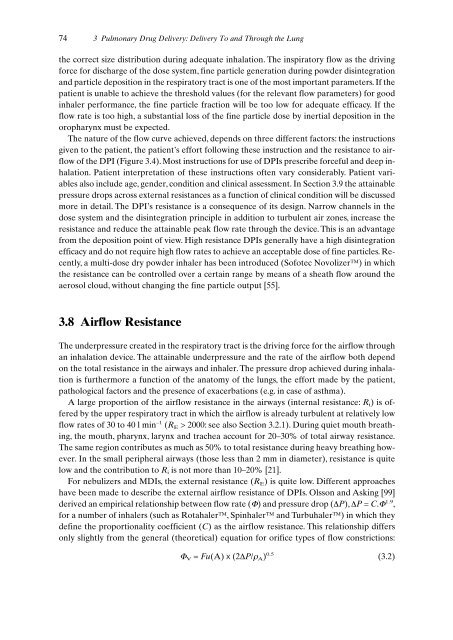
- Page 113 and 114: 76 3 Pulmonary Drug Delivery: Deliv
- Page 115 and 116: 78 3 Pulmonary Drug Delivery: Deliv
- Page 117 and 118: 80 3 Pulmonary Drug Delivery: Deliv
- Page 119 and 120: 82 3 Pulmonary Drug Delivery: Deliv
- Page 121 and 122: 84 3 Pulmonary Drug Delivery: Deliv
- Page 123 and 124: 86 3 Pulmonary Drug Delivery: Deliv
- Page 125 and 126: 4 Cell Specific Delivery of Anti-In
- Page 127 and 128: The sinusoids are lined by the disc
- Page 129 and 130: 4.2.2.2 Phagocytosis and Transcytos
- Page 131 and 132: ther inflammatory cells or accessor
- Page 133 and 134: 4.3 Hepatic Inflammation and Fibros
- Page 135 and 136: process is not yet available. Sever
- Page 137 and 138: this carrier to the KCs.When the ma
- Page 139 and 140: e taken up rapidly by mannose recep
- Page 141 and 142: y the transcriptional regulatory pr
- Page 143 and 144: 4.8 Testing Liver Targeting Prepara
- Page 145 and 146: 4.8 Testing Liver Targeting Prepara
- Page 147 and 148: 4.9 Targeting of Anti-inflammatory
- Page 149 and 150: 4.9 Targeting of Anti-inflammatory
- Page 151 and 152: with monoclonal and bispecific anti
- Page 153 and 154: References 117 [50] Coleman DL, Eur
- Page 155 and 156: References 119 [133] Cronstein BN,
- Page 157 and 158: 5 Delivery of Drugs and Antisense O
- Page 159 and 160: 5.1 Introduction 123 convoluted tub
- Page 161 and 162:
treatment of the targeted cell and
- Page 163 and 164:
CL uptake (ml/min/g) centration pro
- Page 165 and 166:
5.2.1.4 Specific Binding of Alkylgl
- Page 167 and 168:
5.2 Renal Delivery Using Pro-Drugs
- Page 169 and 170:
5.2 Renal Delivery Using Pro-Drugs
- Page 171 and 172:
5.3 Renal Delivery Using Macromolec
- Page 173 and 174:
5.3 Renal Delivery Using Macromolec
- Page 175 and 176:
5.3 Renal Delivery Using Macromolec
- Page 177 and 178:
5.3 Renal Delivery Using Macromolec
- Page 179 and 180:
5.3 Renal Delivery Using Macromolec
- Page 181 and 182:
5.4 Renal Delivary of Antisense Oli
- Page 183 and 184:
5.4 Renal Delivery of Antisense Oli
- Page 185 and 186:
5.4.8 Benefits and Limitations of A
- Page 187 and 188:
via reabsorption from the luminal s
- Page 189 and 190:
References 153 [66] Franssen EJF, M
- Page 191 and 192:
References 155 [145] Van Zwieten PA
- Page 193 and 194:
158 6 A Practical Approach in the D
- Page 195 and 196:
160 6 A Practical Approach in the D
- Page 197 and 198:
162 6 A Practical Approach in the D
- Page 199 and 200:
164 6 A Practical Approach in the D
- Page 201 and 202:
166 6 A Practical Approach in the D
- Page 203 and 204:
168 6 A Practical Approach in the D
- Page 205 and 206:
170 6 A Practical Approach in the D
- Page 207 and 208:
172 7 Vascular Endothelium in Infla
- Page 209 and 210:
174 7 Vascular Endothelium in Infla
- Page 211 and 212:
176 7 Vascular Endothelium in Infla
- Page 213 and 214:
178 7 Vascular Endothelium in Infla
- Page 215 and 216:
180 7 Vascular Endothelium in Infla
- Page 217 and 218:
182 7 Vascular Endothelium in Infla
- Page 219 and 220:
184 7 Vascular Endothelium in Infla
- Page 221 and 222:
186 7 Vascular Endothelium in Infla
- Page 223 and 224:
188 7 Vascular Endothelium in Infla
- Page 225 and 226:
190 7 Vascular Endothelium in Infla
- Page 227 and 228:
192 7 Vascular Endothelium in Infla
- Page 229 and 230:
194 7 Vascular Endothelium in Infla
- Page 231 and 232:
196 7 Vascular Endothelium in Infla
- Page 233 and 234:
8 Strategies for Specific Drug Targ
- Page 235 and 236:
8.2.2 Histogenesis The traditional
- Page 237 and 238:
may become obstructed and compresse
- Page 239 and 240:
8.5 Strategies to Deliver Drugs to
- Page 241 and 242:
8.5 Strategies to Deliver Drugs to
- Page 243 and 244:
larly cytotoxic immune effector cel
- Page 245 and 246:
contributes to limited tumour penet
- Page 247 and 248:
ples onto anti-EGP-2 scFv. Biologic
- Page 249 and 250:
In the case of drug-monoclonal anti
- Page 251 and 252:
cells, the presence of co-stimulato
- Page 253 and 254:
Monomethoxy-polyethylene glycol CH
- Page 255 and 256:
e efficiently loaded into the lipos
- Page 257 and 258:
8.6 Clinical Studies 223 Table 8.5.
- Page 259 and 260:
8.6.3 (Synthetic) (co)Polymers Solu
- Page 261 and 262:
8.8 Conclusions and Future Perspect
- Page 263 and 264:
References 229 [43] Chaouchi NA, Va
- Page 265 and 266:
References 231 [126] Czuczman MS, G
- Page 267 and 268:
234 9 Tumour Vasculature Targeting
- Page 269 and 270:
236 9 Tumour Vasculature Targeting
- Page 271 and 272:
238 9 Tumour Vasculature Targeting
- Page 273 and 274:
240 9 Tumour Vasculature Targeting
- Page 275 and 276:
242 9 Tumour Vasculature Targeting
- Page 277 and 278:
244 9 Tumour Vasculature Targeting
- Page 279 and 280:
246 9 Tumour Vasculature Targeting
- Page 281 and 282:
248 9 Tumour Vasculature Targeting
- Page 283 and 284:
250 9 Tumour Vasculature Targeting
- Page 285 and 286:
252 9 Tumour Vasculature Targeting
- Page 287 and 288:
254 9 Tumour Vasculature Targeting
- Page 289 and 290:
256 10 Phage Display Technology for
- Page 291 and 292:
258 10 Phage Display Technology for
- Page 293 and 294:
260 10 Phage Display Technology for
- Page 295 and 296:
262 10 Phage Display Technology for
- Page 297 and 298:
264 10 Phage Display Technology for
- Page 299 and 300:
266 10 Phage Display Technology for
- Page 301 and 302:
268 10 Phage Display Technology for
- Page 303 and 304:
270 10 Phage Display Technology for
- Page 305 and 306:
272 10 Phage Display Technology for
- Page 307 and 308:
11 Development of Proteinaceous Dru
- Page 309 and 310:
carrier is an homogenous product. I
- Page 311 and 312:
11.3 The Homing Device 11.3 The Hom
- Page 313 and 314:
malian cell lines that have acquire
- Page 315 and 316:
jugates for the delivery of other a
- Page 317 and 318:
11.5 The Linkage Between Drug and C
- Page 319 and 320:
actions are directed towards these
- Page 321 and 322:
11.5 The Linkage Between Drug and C
- Page 323 and 324:
homing potential if the antigen rec
- Page 325 and 326:
ly used promoters include T7 RNA po
- Page 327 and 328:
the baculovirus expression vector,
- Page 329 and 330:
11.8 Recombinant DNA Constructs 297
- Page 331 and 332:
11.8 Recombinant DNA Constructs 299
- Page 333 and 334:
toxic activity. Anthrax and tetanus
- Page 335 and 336:
11.9 Recombinant Domains as Buildin
- Page 337 and 338:
References 305 [16] Milstein C, Wal
- Page 339 and 340:
References 307 [99] Verma R, Boleti
- Page 341 and 342:
12 Use of Human Tissue Slices in Dr
- Page 343 and 344:
are also extensively used in a vari
- Page 345 and 346:
Meanwhile many incubation systems h
- Page 347 and 348:
12.3 Incubation and Culture of Live
- Page 349 and 350:
to investigate the effect of differ
- Page 351 and 352:
The mechanisms of uptake and excret
- Page 353 and 354:
12.6 The Use of Liver Slices in Dru
- Page 355 and 356:
12.7 Efficacy Testing of the Drug T
- Page 357 and 358:
NO x µM 80 60 40 20 * * 12.7 Effic
- Page 359 and 360:
TNFα ng/ml 1.5 1 0.5 0 * Human (n=
- Page 361 and 362:
References 329 [33] Ikejima K, Enom
- Page 363 and 364:
References 331 [109] Dutt A, Priebe
- Page 365 and 366:
334 13 Pharmacokinetic/Pharmacodyna
- Page 367 and 368:
336 13 Pharmacokinetic/Pharmacodyna
- Page 369 and 370:
338 13 Pharmacokinetic/Pharmacodyna
- Page 371 and 372:
340 13 Pharmacokinetic/Pharmacodyna
- Page 373 and 374:
342 13 Pharmacokinetic/Pharmacodyna
- Page 375 and 376:
344 13 Pharmacokinetic/Pharmacodyna
- Page 377 and 378:
346 13 Pharmacokinetic/Pharmacodyna
- Page 379 and 380:
348 13 Pharmacokinetic/Pharmacodyna
- Page 381 and 382:
350 13 Pharmacokinetic/Pharmacodyna
- Page 383 and 384:
352 13 Pharmacokinetic/Pharmacodyna
- Page 385 and 386:
354 13 Pharmacokinetic/Pharmacodyna
- Page 387 and 388:
356 13 Pharmacokinetic/Pharmacodyna
- Page 389 and 390:
358 13 Pharmacokinetic/Pharmacodyna
- Page 391 and 392:
360 13 Pharmacokinetic/Pharmacodyna
- Page 393 and 394:
362 13 Pharmacokinetic/Pharmacodyna
- Page 395 and 396:
364 13 Pharmacokinetic/Pharmacodyna
- Page 397 and 398:
366 13 Pharmacokinetic/Pharmacodyna
- Page 399 and 400:
368 13 Pharmacokinetic/Pharmacodyna
- Page 401 and 402:
370 13 Pharmacokinetic/Pharmacodyna
- Page 403 and 404:
372 14 Drug Targeting Strategy: Scr
- Page 405 and 406:
374 14 Drug Targeting Strategy: Scr