October 2006 Volume 9 Number 4
October 2006 Volume 9 Number 4
October 2006 Volume 9 Number 4

Create successful ePaper yourself
Turn your PDF publications into a flip-book with our unique Google optimized e-Paper software.
Step 5: Instantiation of the technology viewpoint. From the computational viewpoint, the software engineering<br />
process needs to identify the different states and behaviors of the objects specified by designers. From a<br />
technology viewpoint, it means that the software engineering process needs to develop and integrate software<br />
captors into these objects, in order to track the behaviors of the technology objects corresponding to the<br />
information objects. In our example, it needs to identify what events (signals) could be exchanged and, for each<br />
of these events, identify the emitter and the receptor. One of the design patterns widely adopted by the software<br />
engineering community for this kind of problem is the MVC paradigm (Model/View/Control) described by<br />
Buschmann et al. (1996). It is implemented in the Java library "swing/JFC". Each object proposed by the<br />
designers and relevant to this paradigm could be a traceable object.<br />
Conclusion. The reverse engineering of a TEL system described by this use case is initiated by the design<br />
process but concerns mainly the software engineering process which, guided by the RM-ODP framework, aims<br />
to define the dynamic schema of the TEL system from its information specification. The result of the reverse<br />
engineering process is the artifact shown by figure 7. From the enterprise viewpoint, this artifact increases the<br />
quality of the specification provided by designers: even if it wasn't specified, by asking to themselves questions<br />
suggested by RM-ODP, the software engineers have enhanced the Learning Object in order to track its use. This<br />
result could be shared with designers, and generate new kinds of instructional scenarios by taking into account<br />
these tracking possibilities.<br />
The Use Case of a Reengineering of a TEL System<br />
With Chikofsky’s definition in mind (see before), one can say that reengineering a system is relevant to a model<br />
driven approach, in an iterative development process. The main reengineering acts on a TEL system are the<br />
modifications made by the designers on the informational model of the educational system, especially by taken<br />
into account the uses observed during a learning session. We will present here a reengineering use case where<br />
the analysis process provides information to the design process which is useful to understand better the real<br />
sequence of learning objects that each learner performed. With these data, both the informational and the<br />
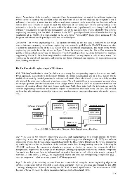
software engineering viewpoints are modified. Figure 8 describes the four steps of the use case, one for each<br />
participating role: software engineering process role, learning process role, analysis process role, design process<br />
role.<br />
: software engineering<br />
process<br />
: produce a<br />
prototype<br />
<br />
: learning process<br />
: execute a<br />
prototype<br />
<br />
: produce an<br />
observable<br />
: design process<br />
: interpret an<br />
information<br />
Figure 8: UML Collaboration Diagram of the Reengineering Use Case<br />
Step 1: the role of the software engineering process. Each reengineering of a system implies its reverse<br />
engineering. In this use case, by applying the reverse engineering pattern (Demeyer et al., 2002), the software<br />
engineering process has developed and integrated captors to the TEL system. This allows the reverse engineering<br />
by producing information on the effects of the decisions made from the engineering viewpoint. Following the<br />
RM-ODP guidelines, the engineering objects are grouped in clusters to reduce the complexity of their<br />
manipulation. Figure 9 is an excerpt of the FreeStyle Learning deployment script on the learners’ computers.<br />
One could see that, even, from an informational viewpoint, there are several objects with a same type (e.g. 3<br />
exercises, 2 slide shows, 2 MCQ), the engineering objects are only the corresponding components (e.g. 1<br />
exercise component, 1 slide show component, 1 MCQ components).<br />
Step 2: the role of the learning process. From the computational viewpoint, these engineering objects are<br />
SCORM components (SCO) provided to each client computer. They are observed and tracked by the LMS<br />
(Learning Management System) following the SCORM technical specification. The transition/state UML<br />
diagram of figure 10 shows the global interaction between the LMS and each SCO.<br />
<br />
<br />
: analysis process<br />
: analyze an<br />
observable<br />
: produce an<br />
information<br />
236