

ADV7174/ADV7179 Chip Scale PAL/NTSC Video ... - Analog Devices
ADV7174/ADV7179 Chip Scale PAL/NTSC Video ... - Analog Devices
ADV7174/ADV7179 Chip Scale PAL/NTSC Video ... - Analog Devices

You also want an ePaper? Increase the reach of your titles
YUMPU automatically turns print PDFs into web optimized ePapers that Google loves.
<strong>ADV7174</strong>/<strong>ADV7179</strong><br />
MODE REGISTER 0 (MR0)<br />
Bits: MR07 – MR00<br />
Address: SR4–SR0 = 00H<br />
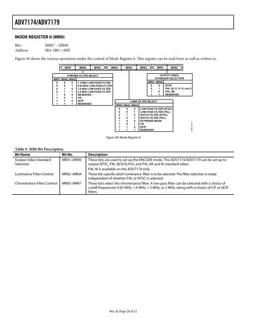
Figure 38 shows the various operations under the control of Mode Register 0. This register can be read from as well as written to.<br />
MR07 MR06 MR05 MR04 MR03 MR02<br />
CHROMA FILTER SELECT<br />
MR07 MR06 MR05<br />
0 0 0 1.3 MHz LOW-PASS FILTER<br />
0 0 1 0.65 MHz LOW-PASS FILTER<br />
0 1 0 1.0 MHz LOW-PASS FILTER<br />
0 1 1 2.0 MHz LOW-PASS FILTER<br />
1 0 0 RESERVED<br />
1 0 1 CIF<br />
1 1 0 QCIF<br />
1 1 1 RESERVED<br />
Rev. B | Page 28 of 52<br />
MR01 MR00<br />
OUTPUT VIDEO<br />
STANDARD SELECTION<br />
MR01 MR00<br />
0 0 <strong>NTSC</strong><br />
0 1 <strong>PAL</strong> (B, D, G, H, and I)<br />
1 0 <strong>PAL</strong> (M)<br />
1 1 RESERVED<br />
LUMA FILTER SELECT<br />
MR04 MR03 MR02<br />
0 0 0 LOW-PASS FILTER (<strong>NTSC</strong>)<br />
0 0 1 LOW-PASS FILTER (<strong>PAL</strong>)<br />
0 1 0 NOTCH FILTER (<strong>NTSC</strong>)<br />
0 0 1 NOTCH FILTER (<strong>PAL</strong>)<br />
1 0 0 EXTENDED MODE<br />
1 0 1 CIF<br />
1 1 0 QCIF<br />
1 1 1 RESERVED 02980-A-037<br />
Figure 38. Mode Register 0<br />
Table 9. MR0 Bit Description<br />
Bit Name Bit No. Description<br />
Output <strong>Video</strong> Standard MR01–MR00 These bits are used to set up the ENCODE mode. The <strong>ADV7174</strong>/<strong>ADV7179</strong> can be set up to<br />
Selection<br />
output <strong>NTSC</strong>, <strong>PAL</strong> (B/D/G/H/I), and <strong>PAL</strong> (M and N) standard video.<br />
<strong>PAL</strong> M is available on the <strong>ADV7174</strong> only.<br />
Luminance Filter Control MR02–MR04 These bits specify which luminance filter is to be selected. The filter selection is made<br />
independent of whether <strong>PAL</strong> or <strong>NTSC</strong> is selected.<br />
Chrominance Filter Control MR05–MR07 These bits select the chrominance filter. A low-pass filter can be selected with a choice of<br />
cutoff frequencies 0.65 MHz, 1.0 MHz, 1.3 MHz, or 2 MHz, along with a choice of CIF or QCIF<br />
filters.


