

ADV7174/ADV7179 Chip Scale PAL/NTSC Video ... - Analog Devices
ADV7174/ADV7179 Chip Scale PAL/NTSC Video ... - Analog Devices
ADV7174/ADV7179 Chip Scale PAL/NTSC Video ... - Analog Devices

Create successful ePaper yourself
Turn your PDF publications into a flip-book with our unique Google optimized e-Paper software.
<strong>ADV7174</strong>/<strong>ADV7179</strong><br />
APPENDIX 3—COPY GENERATION MANAGEMENT SYSTEM (CGMS)<br />
The <strong>ADV7174</strong>/<strong>ADV7179</strong> supports the CGMS, conforming to<br />
the standard. CGMS data is transmitted on Line 20 of the odd<br />
fields and on Line 283 of the even fields. Bits C/W05 and<br />
C/W06 control whether or not CGMS data is output on odd<br />
and even fields. CGMS data can only be transmitted when the<br />
<strong>ADV7174</strong>/ <strong>ADV7179</strong> is configured in <strong>NTSC</strong> mode. The CGMS<br />
data is 20 bits long, the function of each of these bits is as shown<br />
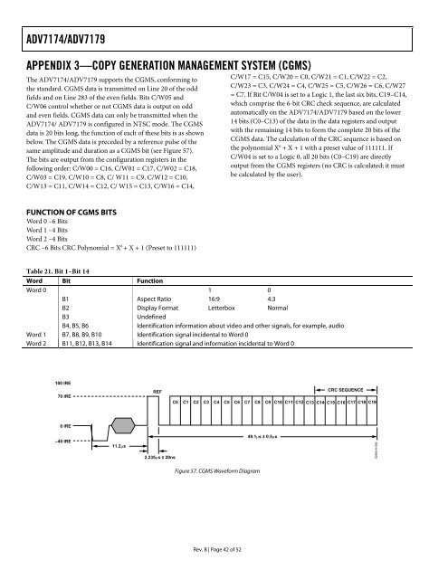
below. The CGMS data is preceded by a reference pulse of the<br />
same amplitude and duration as a CGMS bit (see Figure 57).<br />
The bits are output from the configuration registers in the<br />
following order: C/W00 = C16, C/W01 = C17, C/W02 = C18,<br />
C/W03 = C19, C/W10 = C8, C/ W11 = C9, C/W12 = C10,<br />
C/W13 = C11, C/W14 = C12, C/ W15 = C13, C/W16 = C14,<br />
FUNCTION OF CGMS BITS<br />
Word 0 –6 Bits<br />
Word 1 –4 Bits<br />
Word 2 –4 Bits<br />
CRC –6 Bits CRC Polynomial = X 6 + X + 1 (Preset to 111111)<br />
Rev. B | Page 42 of 52<br />
C/W17 = C15, C/W20 = C0, C/W21 = C1, C/W22 = C2,<br />
C/W23 = C3, C/W24 = C4, C/W25 = C5, C/W26 = C6, C/W27<br />
= C7. If Bit C/W04 is set to a Logic 1, the last six bits, C19–C14,<br />
which comprise the 6-bit CRC check sequence, are calculated<br />
automatically on the <strong>ADV7174</strong>/<strong>ADV7179</strong> based on the lower<br />
14 bits (C0–C13) of the data in the data registers and output<br />
with the remaining 14 bits to form the complete 20 bits of the<br />
CGMS data. The calculation of the CRC sequence is based on<br />
the polynomial X 6 + X + 1 with a preset value of 111111. If<br />
C/W04 is set to a Logic 0, all 20 bits (C0–C19) are directly<br />
output from the CGMS registers (no CRC is calculated; it must<br />
be calculated by the user).<br />
Table 21. Bit 1–Bit 14<br />
Word Bit Function<br />
Word 0 1 0<br />
B1 Aspect Ratio 16:9 4:3<br />
B2 Display Format Letterbox Normal<br />
B3 Undefined<br />
B4, B5, B6 Identification information about video and other signals, for example, audio<br />
Word 1 B7, B8, B9, B10 Identification signal incidental to Word 0<br />
Word 2 B11, B12, B13, B14 Identification signal and information incidental to Word 0<br />
100 IRE<br />
70 IRE<br />
0 IRE<br />
–40 IRE<br />
11.2μs<br />
REF<br />
2.235μs ± 20ns<br />
49.1μs ± 0.5μs<br />
CRC SEQUENCE<br />
C0 C1 C2 C3 C4 C5 C6 C7 C8 C9 C10 C11 C12 C13 C14 C15 C16 C17 C18 C19<br />
Figure 57. CGMS Waveform Diagram<br />
02980-A-056


