

ADV7174/ADV7179 Chip Scale PAL/NTSC Video ... - Analog Devices
ADV7174/ADV7179 Chip Scale PAL/NTSC Video ... - Analog Devices
ADV7174/ADV7179 Chip Scale PAL/NTSC Video ... - Analog Devices

You also want an ePaper? Increase the reach of your titles
YUMPU automatically turns print PDFs into web optimized ePapers that Google loves.
<strong>ADV7174</strong>/<strong>ADV7179</strong><br />
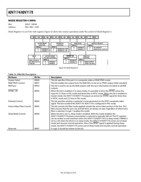
MODE REGISTER 4 (MR4)<br />
Bits: MR47–MR40<br />
Address: SR4–SR0 = 04H<br />
Mode Register 4 is an 8-bit-wide register. Figure 42 shows the various operations under the control of Mode Register 4.<br />
MR47 MR46 MR45 MR44 MR43 MR42<br />
MR47<br />
(0)<br />
ZERO SHOULD<br />
BE WRITTEN TO<br />
THIS BIT<br />
SLEEP MODE<br />
CONTROL<br />
MR46<br />
0 DISABLE<br />
1 ENABLE<br />
ACTIVE VIDEO<br />
FILTER CONTROL<br />
MR45<br />
0 DISABLE<br />
1 ENABLE<br />
PEDESTAL<br />
CONTROL<br />
MR44<br />
0 PEDESTAL OFF<br />
1 PEDESTAL ON<br />
VSYNC_3H<br />
MR43<br />
0 DISABLE<br />
1 ENABLE<br />
Figure 42. Mode Register 4<br />
Rev. B | Page 32 of 52<br />
RGB SYNC<br />
MR42<br />
0 DISABLE<br />
1 ENABLE<br />
MR41 MR40<br />
RGB/YUV<br />
CONTROL<br />
MR41<br />
0 RGB OUTPUT<br />
1 YPbPr OUTPUT<br />
OUTPUT SELECT<br />
MR40<br />
0 YC OUTPUT<br />
1 RGB/YPbPr OUTPUT<br />
Table 14. MR4 Bit Description<br />
Bit Name Bit No. Description<br />
Output Select MR40 This bit specifies if the part is in composite video or RGB/YPbPr mode.<br />
RGB/YPbPr Control MR41 This bit enables the output from the RGB DACs to be set to YPbPr output video standard.<br />
RGB Sync MR42 This bit is used to set up the RGB outputs with the sync information encoded on all RGB<br />
outputs.<br />
VSYNC_3H MR43 When this bit is enabled (1) in slave mode, it is possible to drive the VSYNC active low<br />
input for 2.5 lines in <strong>PAL</strong> mode and three lines in <strong>NTSC</strong> mode. When this bit is enabled in<br />
master mode, the <strong>ADV7174</strong>/<strong>ADV7179</strong> outputs an active low VSYNC signal for three lines<br />
in <strong>NTSC</strong> mode and 2.5 lines in <strong>PAL</strong> mode.<br />
Pedestal Control MR44 This bit specifies whether a pedestal is to be generated on the <strong>NTSC</strong> composite video<br />
signal. This bit is invalid if the <strong>ADV7174</strong>/ <strong>ADV7179</strong> is configured in <strong>PAL</strong> mode.<br />
Active <strong>Video</strong> Filter Control MR45 This bit controls the filter mode applied outside the active video portion of the line. This<br />
filter ensures that the sync rise and fall times are always on spec regardless of which luma<br />
filter is selected. A Logic 1 enables this mode.<br />
Sleep Mode Control MR46 When this bit is set (1), sleep mode is enabled. With this mode enabled, the<br />
<strong>ADV7174</strong>/<strong>ADV7179</strong> power consumption is reduced to typically 200 nA. The I 2 C registers<br />
can be written to and read from when the <strong>ADV7174</strong>/<strong>ADV7179</strong> is in sleep mode. If MR46 is<br />
set to a (0) when the device is in sleep mode, the <strong>ADV7174</strong>/<strong>ADV7179</strong> comes out of sleep<br />
mode and resumes normal operation. Also, if the RESET signal is applied during sleep<br />
mode, the <strong>ADV7174</strong>/<strong>ADV7179</strong> comes out of sleep mode and resumes normal operation.<br />
Reserved MR47 A Logic 0 should be written to this bit.<br />
02980-A-041


