

ADV7174/ADV7179 Chip Scale PAL/NTSC Video ... - Analog Devices
ADV7174/ADV7179 Chip Scale PAL/NTSC Video ... - Analog Devices
ADV7174/ADV7179 Chip Scale PAL/NTSC Video ... - Analog Devices

Create successful ePaper yourself
Turn your PDF publications into a flip-book with our unique Google optimized e-Paper software.
MODE REGISTER 1 (MR1)<br />
Bits: MR17–MR10<br />
Address: SR4–SR0 = 01H<br />
Rev. B | Page 29 of 52<br />
<strong>ADV7174</strong>/<strong>ADV7179</strong><br />
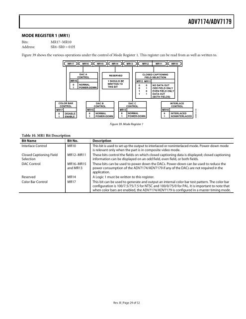
Figure 39 shows the various operations under the control of Mode Register 1. This register can be read from as well as written to.<br />
COLOR BAR<br />
CONTROL<br />
MR17<br />
0 DISABLE<br />
1 ENABLE<br />
MR17 MR16 MR15 MR14 MR13 MR12<br />
DAC A<br />
CONTROL<br />
MR16<br />
0 NORMAL<br />
1 POWER-DOWN<br />
DAC B<br />
CONTROL<br />
MR15<br />
0 NORMAL<br />
1 POWER-DOWN<br />
RESERVED<br />
1 SHOULD BE<br />
WRITTEN TO<br />
THIS BIT<br />
DAC C<br />
CONTROL<br />
MR13<br />
0 NORMAL<br />
1 POWER-DOWN<br />
Figure 39. Mode Register 1<br />
MR11 MR10<br />
CLOSED CAPTIONING<br />
FIELD SELECTION<br />
MR12 MR11<br />
0 0 NO DATA OUT<br />
0 1 ODD FIELD ONLY<br />
1 0 EVEN FIELD ONLY<br />
1 1 DATA OUT<br />
(BOTH FIELDS)<br />
INTERLACE<br />
CONTROL<br />
MR10<br />
0 INTERLACED<br />
1 NONINTERLACED<br />
Table 10. MR1 Bit Description<br />
Bit Name Bit No. Description<br />
Interlace Control MR10 This bit is used to set up the output to interlaced or noninterlaced mode. Power-down mode<br />
is relevant only when the part is in composite video mode.<br />
Closed Captioning Field MR12–MR11 These bits control the fields on which closed captioning data is displayed; closed captioning<br />
Selection<br />
information can be displayed on an odd field, even field, or both fields.<br />
DAC Control MR16–MR15<br />
and MR13<br />
These bits can be used to power down the DACs. Power-down can be used to reduce the<br />
power consumption of the <strong>ADV7174</strong>/<strong>ADV7179</strong> if any of the DACs are not required in the<br />
application.<br />
Reserved MR14 A Logic 1 must be written to this register.<br />
Color Bar Control MR17 This bit can be used to generate and output an internal color bar test pattern. The color bar<br />
configuration is 100/7.5/75/7.5 for <strong>NTSC</strong> and 100/0/75/0 for <strong>PAL</strong>. It is important to note that<br />
when color bars are enabled, the <strong>ADV7174</strong>/<strong>ADV7179</strong> is configured in a master timing mode.<br />
02980-A-039


