The Turbo Air® 3000 Centrifugal Compressor Compressor Handbook
The Turbo Air® 3000 Centrifugal Compressor Compressor Handbook
The Turbo Air® 3000 Centrifugal Compressor Compressor Handbook

Create successful ePaper yourself
Turn your PDF publications into a flip-book with our unique Google optimized e-Paper software.
<strong>The</strong> <strong>Turbo</strong> Air <strong>3000</strong> <strong>Centrifugal</strong> <strong>Compressor</strong> Operator’s Manual<br />
Optional Features<br />
Although the following components are not required for safe operation of the <strong>Turbo</strong> Air <strong>3000</strong> <strong>Compressor</strong>,<br />
they will bring added convenience to the overall operation of the lubrication system. If not<br />
included with the initial compressor package, they may be added at any time.<br />
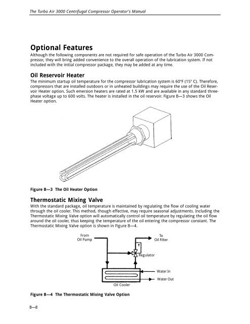
Oil Reservoir Heater<br />
<strong>The</strong> minimum startup oil temperature for the compressor lubrication system is 60°F (15° C). <strong>The</strong>refore,<br />
compressors that are installed outdoors or in unheated buildings may require the use of the Oil Reservoir<br />
Heater option. Such emersion heaters are rated at 1.5 kW and are available in any standard threephase<br />
voltage up to 600 volts. <strong>The</strong> heater is installed in the oil reservoir. Figure B—3 shows the Oil<br />
Heater option.<br />
Figure B—3 <strong>The</strong> Oil Heater Option<br />
<strong>The</strong>rmostatic Mixing Valve<br />
With the standard package, oil temperature is maintained by regulating the flow of cooling water<br />
through the oil cooler. This method, though effective, may require seasonal adjustments. Including the<br />
<strong>The</strong>rmostatic Mixing Valve option will automatically control oil temperature by regulating the oil flow<br />
around the oil cooler, thus keeping the temperature of the oil entering the compressor constant. <strong>The</strong><br />
<strong>The</strong>rmostatic Mixing Valve option is shown in Figure B—4.<br />
Figure B—4 <strong>The</strong> <strong>The</strong>rmostatic Mixing Valve Option<br />
B—8<br />
From<br />
Oil Pump<br />
Oil Cooler<br />
Regulator<br />
To<br />
Oil Filter<br />
Water In<br />
Water Out