
Create successful ePaper yourself
Turn your PDF publications into a flip-book with our unique Google optimized e-Paper software.
Introduction of newly developed towing wind tunnel facility<br />
S. Yoshioka a, T. Kato a, Y. Kohama a, F. Ohta a, M. Tokuyama a<br />
We have built 7 km long testing line in Sunrise beach research facility of Tohoku<br />
University in Hyuga city, Miyazaki, Japan in 2003. In the first 2 km out of total 7 km<br />
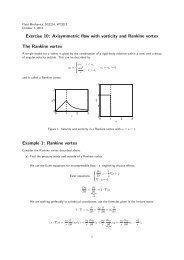
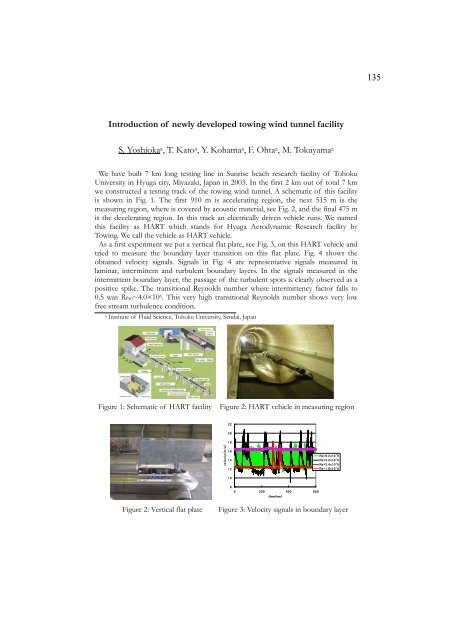
we constructed a testing track of the towing wind tunnel. A schematic of this facility<br />
is shown in Fig. 1. The first 910 m is accelerating region, the next 515 m is the<br />
measuring region, where is covered by acoustic material, see Fig. 2, and the final 475 m<br />
is the decelerating region. In this track an electrically driven vehicle runs. We named<br />
this facility as HART which stands for Hyuga Aerodynamic Research facility by<br />
Towing. We call the vehicle as HART vehicle.<br />
As a first experiment we put a vertical flat plate, see Fig. 3, on this HART vehicle and<br />
tried to measure the boundary layer transition on this flat plate. Fig. 4 shows the<br />
obtained velocity signals. Signals in Fig. 4 are representative signals measured in<br />
laminar, intermittent and turbulent boundary layers. In the signals measured in the<br />
intermittent boundary layer, the passage of the turbulent spots is clearly observed as a<br />
positive spike. The transitional Reynolds number where intermittency factor falls to<br />
0.5 was Re50~4.0×10⁶. This very high transitional Reynolds number shows very low<br />
free stream turbulence condition.<br />
a Institute of Fluid Science, Tohoku University, Sendai, Japan<br />
Figure 1: Schematic of HART facility Figure 2: HART vehicle in measuring region<br />
<br />
<br />
<br />
<br />
<br />
<br />
<br />
<br />
<br />
<br />
<br />
<br />
<br />
<br />
<br />
Figure 2: Vertical flat plate Figure 3: Velocity signals in boundary layer<br />
135