
You also want an ePaper? Increase the reach of your titles
YUMPU automatically turns print PDFs into web optimized ePapers that Google loves.
156<br />
Direct numerical simulation of turbulent flow in a tilted<br />
rotating duct<br />
G. E. M˚artensson ∗ ,G.Brethouwer ∗ and A.V. Johansson ∗<br />
Studying the effects of system rotation on turbulent flow is a most difficult and important<br />
area of turbulence research. This area is of fundamental academic interest, as well<br />
as of considerable industrial importance concerning applications such as centrifugal<br />
separators and turbines. In centrifugal separator applications, the flow is subjected<br />
to extremely high system rotation rates, the Rotation number being typically around<br />
or above one. At these high Rotation numbers, the flow field in a plane channel is<br />
strongly asymmetric and contains large zones of relaminarized flow on the stable side.<br />
Recent experimental 1 and numerical studies 2 of the turbulent flow in rapidly rotating<br />
square ducts have shown the importance of the specific geometric configuration.<br />
In the present study, a direct numerical simulation of turbulent flow in a rotating<br />
tilted square duct is carried out to further probe these geometric effects. The rotation<br />
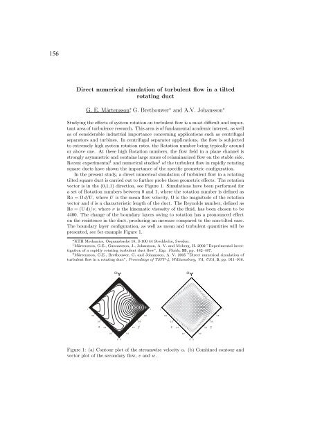
vector is in the (0,1,1) direction, see Figure 1. Simulations have been performed for<br />
a set of Rotation numbers between 0 and 1, where the rotation number is defined as<br />
Ro = Ω d/U, whereU is the mean flow velocity, Ω is the magnitude of the rotation<br />
vector and d is a characteristic length of the duct. The Reynolds number, defined as<br />
Re = (U d)/ν, whereν isthekinematicviscosityofthefluid,hasbeenchosentobe<br />
4400. The change of the boundary layers owing to rotation has a pronounced effect<br />
on the resistence in the duct, producing an increase compared to the non-tilted case.<br />
The boundary layer configuration, as well as mean and turbulent quantities will be<br />
presented, see for example Figure 1.<br />
∗ <strong>KTH</strong> <strong>Mechanics</strong>, Osquarsbacke 18, S-100 44 Stockholm, Sweden.<br />
1 M˚artensson, G.E., Gunnarsson, J., Johansson, A. V. and Moberg, H. 2002 ”Experimental investigation<br />
of a rapidly rotating turbulent duct flow”, Exp. Fluids, 33, pp. 482–487.<br />
2 M˚artensson, G.E., Brethouwer, G. and Johansson, A. V. 2005 ”Direct numerical simulation of<br />
turbulent flow in a rotating duct”, Proceedings of TSFP-4, Williamsburg, VA, USA, 3, pp. 911–916.<br />
1<br />
0.8<br />
0.6<br />
z<br />
0.4<br />
0.2<br />
Ω Ω<br />
0 0<br />
0.2<br />
0.4<br />
0.6<br />
y<br />
0.8<br />
1<br />
Figure 1: (a) Contour plot of the streamwise velocity u. (b) Combined contour and<br />
vector plot of the secondary flow, v and w.<br />
1<br />
0.8<br />
0.6<br />
z<br />
0.4<br />
0.2<br />
0 0<br />
0.2<br />
0.4<br />
0.6<br />
y<br />
0.8<br />
1