
Create successful ePaper yourself
Turn your PDF publications into a flip-book with our unique Google optimized e-Paper software.
176<br />
Modeling Cavitation on a Wing Section using LES<br />
T. Persson a, N. Berchiche a, G. Bark a, N. Wikström b and C. Fureby a,b<br />
Cavitation can occur in a wide range of liquid flows, especially in marine<br />
applications e.g. around rudders and propellers and consequently cavitation research is<br />
a very important topic for the marine industry. To enable modelling of the complex<br />
behaviour of cavitating flow, time accurate, high resolution simulation of a two phase<br />
flow problem with mass transfer is required. Presently the flow dynamics is captured<br />
by employing Large Eddy Simulation1 (LES) of the incompressible flow equations,<br />
whereas water and vapour is separated using an interface capturing two phase model.<br />
The mass transfer model used is based on the work by Kunz et al. 2. In this model<br />
proportionality between the liquid volume fraction and the amount by which the<br />
pressure is below the vapour pressure is used to model the transformation from liquid<br />
to vapour. The transformation of vapour to liquid is modelled using a simplified form<br />
of the Ginzburg-Landau potential.<br />
The aim of this ongoing work is to study the possibility to simulate early and large<br />
scale developments that by experimental studies3 are confirmed to result in cavitation<br />
erosion.<br />
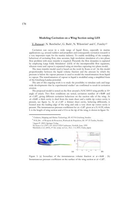
The proposed model is tested on the flow around a NACA0015 wing profile at 10o angle of attack. Two flow conditions are tested, cavitation number 0.<br />
69 and<br />
1.<br />
07 , giving different cavitation behaviour on the suction side of the wing. At<br />
0.<br />
69 a thick cavity is shed from the main sheet and a stable tip vortex cavity is<br />
present, see figure 1a. At 1.<br />
07 a thinner sheet cavity, behaving differently, is<br />
located near the leading edge of the wing and only a very short tip vortex cavity is<br />
present. The instantaneous pressure coefficient for 1.<br />
07 given at z/L=0.59, where<br />
L is the length of wing section and z=0 is at the tip of the wing, is shown in figure 1b.<br />
a<br />
Chalmers, Shipping and Marine Technology, SE-412 96 Göteborg, Sweden.<br />
b<br />
FOI, Div . of Weapons & Protection, Warheads & Propulsion, SE-147 25 Tumba, Sweden.<br />
1 Sagaut P. (2001) Springer Verlag.<br />
2 R. Kunz et al. (1997) 14th AIAA CFD Conference, Norfolk, June, 1999<br />
3 Berchiche et al. (2003), 5th Int. symp. on Cav., Nov. 1-4, 2003, Osaka, Japan<br />
(a) (b)<br />
Figure 1: (a) Isosurface of the instantaneous volume fraction at 0.<br />
69 . (b)<br />
Instantaneous pressure coefficient on the surface of the wing section at 1.<br />
07 .