
Create successful ePaper yourself
Turn your PDF publications into a flip-book with our unique Google optimized e-Paper software.
164<br />
Flowcontrol with crosswise groves in diffusor flows<br />
R. Meyer a, W. Hage a and C.O. Paschereit b<br />
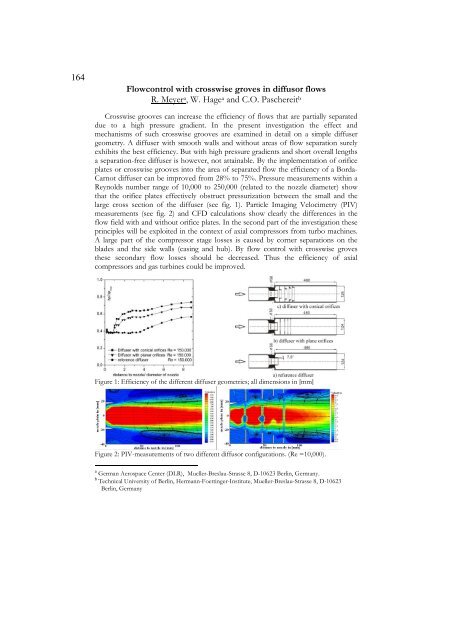
Crosswise grooves can increase the efficiency of flows that are partially separated<br />
due to a high pressure gradient. In the present investigation the effect and<br />
mechanisms of such crosswise grooves are examined in detail on a simple diffuser<br />
geometry. A diffuser with smooth walls and without areas of flow separation surely<br />
exhibits the best efficiency. But with high pressure gradients and short overall lengths<br />
a separation-free diffuser is however, not attainable. By the implementation of orifice<br />
plates or crosswise grooves into the area of separated flow the efficiency of a Borda-<br />
Carnot diffuser can be improved from 28% to 75%. Pressure measurements within a<br />
Reynolds number range of 10,000 to 250,000 (related to the nozzle diameter) show<br />
that the orifice plates effectively obstruct pressurization between the small and the<br />
large cross section of the diffuser (see fig. 1). Particle Imaging Velocimetry (PIV)<br />
measurements (see fig. 2) and CFD calculations show clearly the differences in the<br />
flow field with and without orifice plates. In the second part of the investigation these<br />
principles will be exploited in the context of axial compressors from turbo machines.<br />
A large part of the compressor stage losses is caused by corner separations on the<br />
blades and the side walls (casing and hub). By flow control with crosswise groves<br />
these secondary flow losses should be decreased. Thus the efficiency of axial<br />
compressors and gas turbines could be improved.<br />
Figure 1: Efficiency of the different diffuser geometries; all dimensions in [mm]<br />
Figure 2: PIV-measurements of two different diffusor configurations. (Re =10,000).<br />
a German Aerospace Center (DLR), Mueller-Breslau-Strasse 8, D-10623 Berlin, Germany.<br />
b Technical University of Berlin, Hermann-Foettinger-Institute, Mueller-Breslau-Strasse 8, D-10623<br />
Berlin, Germany