
You also want an ePaper? Increase the reach of your titles
YUMPU automatically turns print PDFs into web optimized ePapers that Google loves.
180<br />
Modelling buoyancy driven displacement ventilation<br />
S. D. Sandbach a<br />
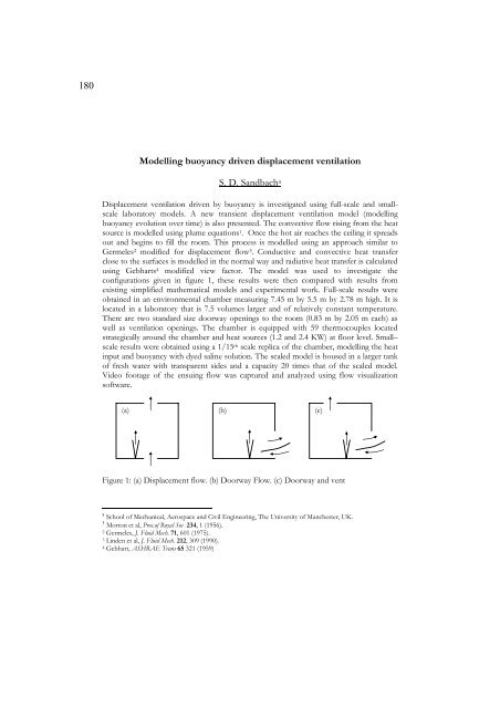
Displacement ventilation driven by buoyancy is investigated using full-scale and smallscale<br />
laboratory models. A new transient displacement ventilation model (modelling<br />
buoyancy evolution over time) is also presented. The convective flow rising from the heat<br />
source is modelled using plume equations 1. Once the hot air reaches the ceiling it spreads<br />
out and begins to fill the room. This process is modelled using an approach similar to<br />
Germeles 2 modified for displacement flow 3. Conductive and convective heat transfer<br />
close to the surfaces is modelled in the normal way and radiative heat transfer is calculated<br />
using Gebharts 4 modified view factor. The model was used to investigate the<br />
configurations given in figure 1, these results were then compared with results from<br />
existing simplified mathematical models and experimental work. Full-scale results were<br />
obtained in an environmental chamber measuring 7.45 m by 5.5 m by 2.78 m high. It is<br />
located in a laboratory that is 7.5 volumes larger and of relatively constant temperature.<br />
There are two standard size doorway openings to the room (0.83 m by 2.05 m each) as<br />
well as ventilation openings. The chamber is equipped with 59 thermocouples located<br />
strategically around the chamber and heat sources (1.2 and 2.4 KW) at floor level. Small–<br />
scale results were obtained using a 1/15 th scale replica of the chamber, modelling the heat<br />
input and buoyancy with dyed saline solution. The scaled model is housed in a larger tank<br />
of fresh water with transparent sides and a capacity 20 times that of the scaled model.<br />
Video footage of the ensuing flow was captured and analyzed using flow visualization<br />
software.<br />
(a) (b)<br />
Figure 1: (a) Displacement flow. (b) Doorway Flow. (c) Doorway and vent<br />
a<br />
School of Mechanical, Aerospace and Civil Engineering, The University of Manchester, UK.<br />
1<br />
Morton et al, Proc.of Royal Soc 234, 1 (1956).<br />
2 Germeles, J. Fluid Mech. 71, 601 (1975).<br />
3 Linden et al, J. Fluid Mech. 212, 309 (1990).<br />
4 Gebhart, ASHRAE Trans 65 321 (1959)<br />
(c)