

SPIRE Design Description - Research Services
SPIRE Design Description - Research Services
SPIRE Design Description - Research Services

You also want an ePaper? Increase the reach of your titles
YUMPU automatically turns print PDFs into web optimized ePapers that Google loves.
Draft <strong>SPIRE</strong> <strong>Design</strong> <strong>Description</strong> Document<br />
The required Absolute Position Error (APE) for Herschel (3.7 arc seconds) corresponds to 11%, 6%, and 3%<br />
signal loss at 250, 350, and 500 µm respectively. The corresponding figures for the goal APE value (1.5")<br />
are 2%, 1%, and 0.5%. For most observations, 11% is not acceptable, but 2% is. Therefore, the required<br />
APE is not good enough to allow accurate photometry at 250 µm without peaking up, but the goal is<br />
sufficient to allow this.<br />
In order to avoid calibration errors due to satellite pointing errors or inaccurate knowledge of the source coordinates,<br />
it is envisaged that many point source observations will be carried out by making a 7-point map<br />
(POF2). The BSM is used to do to do small map 7-point hexagonal jiggle map with spacing θ arcsec., as<br />
shown in Figure 5-5b. A suitable value for θ is ~ 6 arc seconds: this spacing is 1/3 of the beam at 250 µm (so<br />
consistent with full sampling), and is almost twice the APE. From such a 7-point map, the total flux of the<br />
source can be computed, and the source position can be recovered with an accuracy that depends on the S/N.<br />
The central position is made to coincide with one of sets of three overlapping detectors to allow<br />
simultaneous optimised observations in the three bands. The chop throw can be set at any desired value<br />
within the available range. A value of 126” improves the overall efficiency by allowing the source to be<br />
observed all the time in all bands.<br />
5.3.2 Jiggle Mapping (POF3 and POF4)<br />
Jiggle-map mode is for mapping objects or regions that are extended with respect to the <strong>SPIRE</strong> beam but<br />
smaller than a few arcminutes in size.<br />
The BSM is used to make an n-point jiggle map while chopping with a throw greater than the size of the<br />
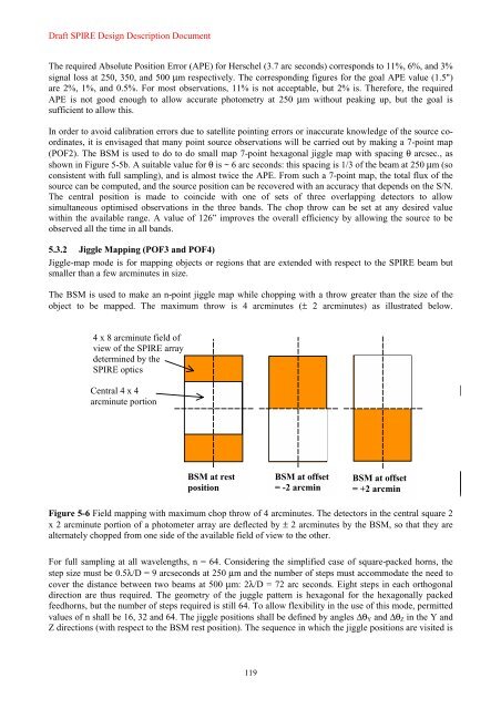
object to be mapped. The maximum throw is 4 arcminutes (± 2 arcminutes) as illustrated below.<br />
4 x 8 arcminute field of<br />
view of the <strong>SPIRE</strong> array<br />
determined by the<br />
<strong>SPIRE</strong> optics<br />
Central 4 x 4<br />
arcminute portion<br />
BSM at rest<br />
position<br />
Figure 5-6 Field mapping with maximum chop throw of 4 arcminutes. The detectors in the central square 2<br />
x 2 arcminute portion of a photometer array are deflected by ± 2 arcminutes by the BSM, so that they are<br />
alternately chopped from one side of the available field of view to the other.<br />
For full sampling at all wavelengths, n = 64. Considering the simplified case of square-packed horns, the<br />
step size must be 0.5λ/D = 9 arcseconds at 250 µm and the number of steps must accommodate the need to<br />
cover the distance between two beams at 500 µm: 2λ/D = 72 arc seconds. Eight steps in each orthogonal<br />
direction are thus required. The geometry of the juggle pattern is hexagonal for the hexagonally packed<br />
feedhorns, but the number of steps required is still 64. To allow flexibility in the use of this mode, permitted<br />
values of n shall be 16, 32 and 64. The jiggle positions shall be defined by angles ∆θY and ∆θZ in the Y and<br />
Z directions (with respect to the BSM rest position). The sequence in which the jiggle positions are visited is<br />
119<br />
BSM at offset<br />
= -2 arcmin<br />
BSM at offset<br />
= +2 arcmin


