

SPIRE Design Description - Research Services
SPIRE Design Description - Research Services
SPIRE Design Description - Research Services

Create successful ePaper yourself
Turn your PDF publications into a flip-book with our unique Google optimized e-Paper software.
Draft <strong>SPIRE</strong> <strong>Design</strong> <strong>Description</strong> Document<br />
change in the OPD of ~ 12 cm or 3 cm in actual mirror movement. In order to Nyquist sample the<br />
interferogram at the highest frequency present in the optical band (50 cm -1 ) , the optical path difference must<br />
be sampled every 20 microns, or every 5 microns of actual mirror movement.<br />
The most efficient method of operating an FTS is the so-called rapid scanning method. Here, the mirror is<br />
kept in constant motion while the signal and mirror position are sampled. This method of operation<br />
effectively transforms the optical frequency to audio frequencies by the relationship f = vopdσ. Where f is the<br />
detection frequency, vopd the rate of change of the optical path difference and σ the optical frequency. The<br />
maximum OPD velocity required will be determined by the frequency response of the detectors. For an<br />
assumed detector response of 20 Hz the maximum vopd will be 0.4 cm/s or 0.1 cm/s in actual mirror speed. In<br />
fact some “head room” may required in case of problems with microphonic interference so the maximum<br />
velocity requirement on the mirror mechanism has been set at 0.2 cm/s.<br />
I<br />
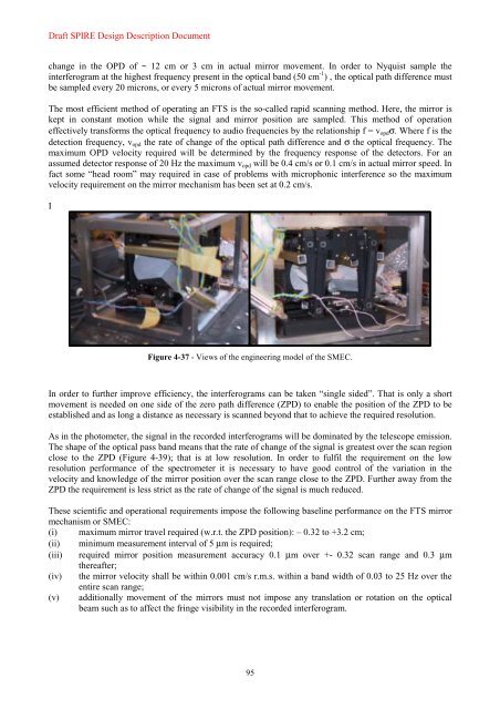
Figure 4-37 - Views of the engineering model of the SMEC.<br />
In order to further improve efficiency, the interferograms can be taken “single sided”. That is only a short<br />
movement is needed on one side of the zero path difference (ZPD) to enable the position of the ZPD to be<br />
established and as long a distance as necessary is scanned beyond that to achieve the required resolution.<br />
As in the photometer, the signal in the recorded interferograms will be dominated by the telescope emission.<br />
The shape of the optical pass band means that the rate of change of the signal is greatest over the scan region<br />
close to the ZPD (Figure 4-39); that is at low resolution. In order to fulfil the requirement on the low<br />
resolution performance of the spectrometer it is necessary to have good control of the variation in the<br />
velocity and knowledge of the mirror position over the scan range close to the ZPD. Further away from the<br />
ZPD the requirement is less strict as the rate of change of the signal is much reduced.<br />
These scientific and operational requirements impose the following baseline performance on the FTS mirror<br />
mechanism or SMEC:<br />
(i) maximum mirror travel required (w.r.t. the ZPD position): – 0.32 to +3.2 cm;<br />
(ii) minimum measurement interval of 5 µm is required;<br />
(iii) required mirror position measurement accuracy 0.1 µm over +- 0.32 scan range and 0.3 µm<br />
thereafter;<br />
(iv) the mirror velocity shall be within 0.001 cm/s r.m.s. within a band width of 0.03 to 25 Hz over the<br />
entire scan range;<br />
(v) additionally movement of the mirrors must not impose any translation or rotation on the optical<br />
beam such as to affect the fringe visibility in the recorded interferogram.<br />
95


