

SPIRE Design Description - Research Services
SPIRE Design Description - Research Services
SPIRE Design Description - Research Services

You also want an ePaper? Increase the reach of your titles
YUMPU automatically turns print PDFs into web optimized ePapers that Google loves.
Draft <strong>SPIRE</strong> <strong>Design</strong> <strong>Description</strong> Document<br />
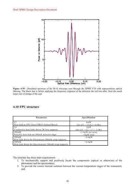
Figure 4-39 - Simulated spectrum of the 80 K telescope seen through the <strong>SPIRE</strong> FTS with representation optical<br />
filtering. The black line is before applying the frequency response of the detectors the red line after. Note the much<br />
larger rate of change of the sign<br />
4.10 FPU structure<br />
Parameter Specification<br />
L1<br />
Heat leak to FPU from FIRST Optical Bench<br />
L0<br />
Conductive heat leaks down 2K box supports<br />
300mK<br />
Parasitic heat leak on 300mK detector stage<br />
300mK<br />
Heat leak down the Photometer 300mK strap supports<br />
300mK<br />
Heat leak down the Spectrometer 300mK strap supports<br />
The structure has three main requirements:<br />
1. To mechanically support and positively locate the components (optical or otherwise) of the<br />
photometer and the spectrometer;<br />
2. To provide the correct thermal isolation between the various temperature stages of the instrument;<br />
and<br />
98<br />
6mW<br />
(for ∆T = 11-4.2 = 6.8K)<br />
1mW<br />
(for ∆T = 4.2 - 1.7 = 2.5K)<br />


