

SPIRE Design Description - Research Services
SPIRE Design Description - Research Services
SPIRE Design Description - Research Services

Create successful ePaper yourself
Turn your PDF publications into a flip-book with our unique Google optimized e-Paper software.
Draft <strong>SPIRE</strong> <strong>Design</strong> <strong>Description</strong> Document<br />
edge of the FOV. The induced contrast reduction is not negligible but small compared with other sources,<br />
notably alignment tolerances.<br />
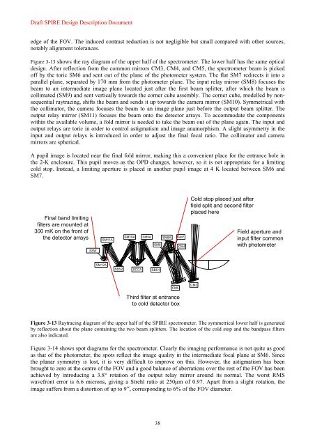
Figure 3-13 shows the ray diagram of the upper half of the spectrometer. The lower half has the same optical<br />
design. After reflection from the common mirrors CM3, CM4, and CM5, the spectrometer beam is picked<br />
off by the toric SM6 and sent out of the plane of the photometer system. The flat SM7 redirects it into a<br />
parallel plane, separated by 170 mm from the photometer plane. The input relay mirror (SM8) focuses the<br />
beam to an intermediate image plane located just after the first beam splitter, after which the beam is<br />
collimated (SM9) and sent vertically towards the corner cube assembly. The corner cube, modelled by nonsequential<br />
raytracing, shifts the beam and sends it up towards the camera mirror (SM10). Symmetrical with<br />
the collimator, the camera focuses the beam to an image plane just before the output beam splitter. The<br />
output relay mirror (SM11) focuses the beam onto the detector arrays. To accommodate the components<br />
within the available volume, a fold mirror is needed to take the beam out of the plane again. The input and<br />
output relays are toric in order to control astigmatism and image anamorphism. A slight asymmetry in the<br />
input and output relays is introduced in order to adjust the final focal ratio. The collimator and camera<br />
mirrors are spherical.<br />
A pupil image is located near the final fold mirror, making this a convenient place for the entrance hole in<br />
the 2-K enclosure. This pupil moves as the OPD changes, however, so it is not appropriate for a limiting<br />
cold stop. Instead, a limiting aperture is placed in another pupil image at 4 K located between SM6 and<br />
SM7.<br />
Final band limiting<br />
filters are mounted at<br />
300 mK on the front of<br />
the detector arrays<br />
Det<br />
SSW<br />
SM11A Rout<br />
Fold<br />
SM12A<br />
BS2 SBS2<br />
Cam<br />
SM10A<br />
CC<br />
SCCA<br />
Coll SM9A SM8A Rin<br />
M6s<br />
SM6<br />
BS1<br />
SBS1<br />
38<br />
M7s SM7<br />
M5 CM5<br />
M4<br />
Third filter at entrance<br />
to cold detector box<br />
CM4<br />
Cold stop placed just after<br />
field split and second filter<br />
placed here<br />
CM3 M3<br />
Field aperture and<br />
input filter common<br />
with photometer<br />
Figure 3-13 Raytracing diagram of the upper half of the <strong>SPIRE</strong> spectrometer. The symmetrical lower half is generated<br />
by reflection about the plane containing the two beam splitters. The location of the cold stop and the bandpass filters<br />
are also indicated.<br />
Figure 3-14 shows spot diagrams for the spectrometer. Clearly the imaging performance is not quite as good<br />
as that of the photometer, the spots reflect the image quality in the intermediate focal plane at SM6. Since<br />
the planar symmetry is lost, it is very difficult to improve on this. However, the astigmatism has been<br />
brought to zero at the centre of the FOV and a good balance of aberrations over the rest of the FOV has been<br />
achieved by introducing a 3.8° rotation of the output relay mirror around its normal. The worst RMS<br />
wavefront error is 6.6 microns, giving a Strehl ratio at 250µm of 0.97. Apart from a slight rotation, the<br />
image suffers from a distortion of up to 9′′, corresponding to 6% of the FOV diameter.


