

SPIRE Design Description - Research Services
SPIRE Design Description - Research Services
SPIRE Design Description - Research Services

Create successful ePaper yourself
Turn your PDF publications into a flip-book with our unique Google optimized e-Paper software.
Draft <strong>SPIRE</strong> <strong>Design</strong> <strong>Description</strong> Document<br />
Transmission<br />
1<br />
0.9<br />
0.8<br />
0.7<br />
0.6<br />
0.5<br />
0.4<br />
0.3<br />
0.2<br />
0.1<br />
0<br />
10 30 50 70<br />
Wavenumber [cm-1]<br />
90 110 130<br />
41<br />
25.5cm-1 HPE<br />
37cm-1 LPE<br />
43cm-1<br />
75cm-1<br />
90cm-1<br />
160cm-1<br />
Total transmission<br />
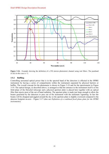
Figure 3-16 - Example showing the definition of a 350 micron photometer channel using real filters. The passband<br />
(λ/∆λ) in this case is ~3.<br />
3.5.2 Baffling<br />
Controlling unwanted optical power that is in the spectral band of the detectors is effected in the <strong>SPIRE</strong><br />
instrument by having a series of compartments within the instrument separated by physical barriers or<br />
baffles. The overall concept for the photometer is shown in Figure 3-18 and for the spectrometer in Figure<br />
3-19. The optical design, as described above, is arranged so that the entrance to the instrument itself is at the<br />
field plane of the Herschel telescope and a physical aperture plate is placed here together with an optical<br />
filter that rejects most of the out of band radiation. The aperture plate is made just large enough to allow the<br />
beams generated by the detectors to pass out of the instrument with the minimum vignetting. In fact the<br />
beams will be chopped and jiggled around the sky so the aperture plate is slightly oversized compared to the<br />
detector footprint on-axis – Figure 3-17 (also see Definition of a combined focal plane plate for the <strong>SPIRE</strong><br />
instruments).


