

SPIRE Design Description - Research Services
SPIRE Design Description - Research Services
SPIRE Design Description - Research Services

Create successful ePaper yourself
Turn your PDF publications into a flip-book with our unique Google optimized e-Paper software.
Draft <strong>SPIRE</strong> <strong>Design</strong> <strong>Description</strong> Document<br />
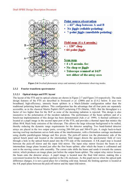
Figure 2-6 Overlaid photometer arrays and summary of photometer observing modes.<br />
2.3.2 Fourier transform spectrometer<br />
2.3.2.1 Optical design and FPU layout<br />
The layout of the FTS and its optical scheme are shown in Figure 2-7 and Figure 2-8 respectively. The main<br />
design features of the FTS are described in Swinyard et al. (2000) and in §3.4.2 below. It uses two<br />
broadband, high-efficiency, intensity beam splitters in a Mach-Zehnder configuration rather than the<br />
traditional polarising beam splitters. This configuration has the advantage that all four ports are separately<br />
accessible, as in the classical Martin Puplett (M-P) polarising FTS (Martin, 1982). But the throughput is a<br />
factor of two higher than for the M-P as none of the incoming radiation is rejected. This design is also<br />
insensitive to the polarisation of the incident radiation. The performance of the beam splitters and of a<br />
bench-top implementation of this design has been demonstrated (Ade et al. 1999). A thermal calibrator is<br />
located at a pupil image in the second input port of the FTS, and provides a thermal input that mimics the<br />
dilute 80-K black body emission of the telescope. This allows the large telescope background to be nulled,<br />
thereby reducing the dynamic range requirements for the detector sampling. Two band-limited detector<br />
arrays are placed in the two output ports, covering 200-300 µm and 300-670 µm. A single back-to-back<br />
moving roof-top mechanism serves both arms of the interferometer, with a frictionless carriage mechanism<br />
using double parallelogram linkage and flex pivots. The pick-off mirror (on the photometer side of the<br />
optical bench panel and located at the intermediate field image) directs the spectrometer field of view<br />
through a hole in the optical bench panel into the FTS side of the instrument. A 4-K pupil stop is located<br />
between the pick-off mirror and the input fold mirror. The input relay mirror focuses the beam to an<br />
intermediate image plane located just after the first beam splitter, after which the beam is collimated and<br />
sent to the moving corner cube assembly. The corner cube shifts the beam and sends it towards the camera<br />
mirror, which produces an image plane just before the output beam splitter. The output relay mirror focuses<br />
the beam onto the detector arrays. A pupil image is located near the final fold mirror, making this a<br />
convenient location for the entrance aperture to the 2-K enclosure. As this pupil moves when the optical path<br />
difference changes, it is not a good place for a limiting cold stop. Instead, the limiting aperture is located at<br />
the 4-K pupil plane between the pick-off mirror and the input fold mirror.<br />
16


