

SPIRE Design Description - Research Services
SPIRE Design Description - Research Services
SPIRE Design Description - Research Services

Create successful ePaper yourself
Turn your PDF publications into a flip-book with our unique Google optimized e-Paper software.
Draft <strong>SPIRE</strong> <strong>Design</strong> <strong>Description</strong> Document<br />
~12 mm<br />
~100 mm<br />
40<br />
~20 mm<br />
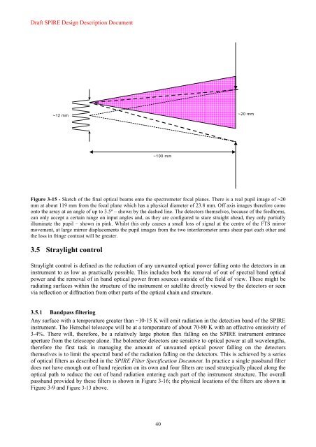
Figure 3-15 - Sketch of the final optical beams onto the spectrometer focal planes. There is a real pupil image of ~20<br />
mm at about 119 mm from the focal plane which has a physical diameter of 23.8 mm. Off axis images therefore come<br />
onto the array at an angle of up to 3.5º – shown by the dashed line. The detectors themselves, because of the feedhorns,<br />
can only accept a certain range on input angles and, as they are configured to stare straight ahead, they only partially<br />
illuminate the pupil – shown in pink. Whilst this only causes a small loss of signal at the centre of the FTS mirror<br />
movement, at large mirror displacements the pupil images from the two interferometer arms shear past each other and<br />
the loss in fringe contrast will be greater.<br />
3.5 Straylight control<br />
Straylight control is defined as the reduction of any unwanted optical power falling onto the detectors in an<br />
instrument to as low as practically possible. This includes both the removal of out of spectral band optical<br />
power and the removal of in band optical power from sources outside of the field of view. These might be<br />
radiating surfaces within the structure of the instrument or satellite directly viewed by the detectors or seen<br />
via reflection or diffraction from other parts of the optical chain and structure.<br />
3.5.1 Bandpass filtering<br />
Any surface with a temperature greater than ~10-15 K will emit radiation in the detection band of the <strong>SPIRE</strong><br />
instrument. The Herschel telescope will be at a temperature of about 70-80 K with an effective emissivity of<br />
3-4%. There will, therefore, be a relatively large photon flux falling on the <strong>SPIRE</strong> instrument entrance<br />
aperture from the telescope alone. The bolometer detectors are sensitive to optical power at all wavelengths,<br />
therefore the first task in managing the amount of unwanted optical power falling on the detectors<br />
themselves is to limit the spectral band of the radiation falling on the detectors. This is achieved by a series<br />
of optical filters as described in the <strong>SPIRE</strong> Filter Specification Document. In practice a single passband filter<br />
does not have enough out of band rejection on its own and four filters are used strategically placed along the<br />
optical path to reduce the out of band radiation entering each part of the instrument structure. The overall<br />
passband provided by these filters is shown in Figure 3-16; the physical locations of the filters are shown in<br />
Figure 3-9 and Figure 3-13 above.


