Setup and Assembling Bookeye 3 - Image Access Inc.
Setup and Assembling Bookeye 3 - Image Access Inc.
Setup and Assembling Bookeye 3 - Image Access Inc.

You also want an ePaper? Increase the reach of your titles
YUMPU automatically turns print PDFs into web optimized ePapers that Google loves.
A.2.4.4<br />
Lamp position control mode<br />
The position of the lamps <strong>and</strong> their maximum travel distance can easily be checked<br />
through the values shown in the keyboard display in this control mode.<br />
The scanner must be in the “lamp initialization mode”. To switch the scanner to the “lamp<br />
initialization mode”, use the key combination as described in chapter A.2.4.1.<br />
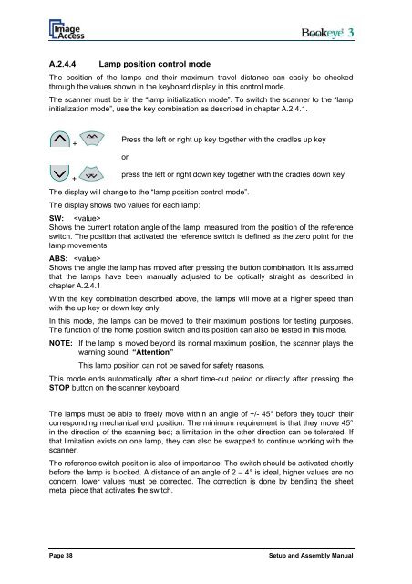
+<br />
Press the left or right up key together with the cradles up key<br />
or<br />
+<br />
press the left or right down key together with the cradles down key<br />
The display will change to the “lamp position control mode”.<br />
The display shows two values for each lamp:<br />
SW: <br />
Shows the current rotation angle of the lamp, measured from the position of the reference<br />
switch. The position that activated the reference switch is defined as the zero point for the<br />
lamp movements.<br />
ABS: <br />
Shows the angle the lamp has moved after pressing the button combination. It is assumed<br />
that the lamps have been manually adjusted to be optically straight as described in<br />
chapter A.2.4.1<br />
With the key combination described above, the lamps will move at a higher speed than<br />
with the up key or down key only.<br />
In this mode, the lamps can be moved to their maximum positions for testing purposes.<br />
The function of the home position switch <strong>and</strong> its position can also be tested in this mode.<br />
NOTE: If the lamp is moved beyond its normal maximum position, the scanner plays the<br />
warning sound: “Attention”<br />
This lamp position can not be saved for safety reasons.<br />
This mode ends automatically after a short time-out period or directly after pressing the<br />
STOP button on the scanner keyboard.<br />
The lamps must be able to freely move within an angle of +/- 45° before they touch their<br />
corresponding mechanical end position. The minimum requirement is that they move 45°<br />
in the direction of the scanning bed; a limitation in the other direction can be tolerated. If<br />
that limitation exists on one lamp, they can also be swapped to continue working with the<br />
scanner.<br />
The reference switch position is also of importance. The switch should be activated shortly<br />
before the lamp is blocked. A distance of an angle of 2 – 4° is ideal, higher values are no<br />
concern, lower values must be corrected. The correction is done by bending the sheet<br />
metal piece that activates the switch.<br />
Page 38<br />
<strong>Setup</strong> <strong>and</strong> Assembly Manual