Alma Mater Studiorum Universit`a degli Studi di Bologna ... - Inaf
Alma Mater Studiorum Universit`a degli Studi di Bologna ... - Inaf
Alma Mater Studiorum Universit`a degli Studi di Bologna ... - Inaf

Create successful ePaper yourself
Turn your PDF publications into a flip-book with our unique Google optimized e-Paper software.
.2. Images 139<br />
2 4 6<br />
2 4 6 8 10<br />
35 48 30<br />
(g)<br />
15<br />
DECLINATION (J2000)<br />
00<br />
47 45<br />
30<br />
15<br />
00<br />
02 09 43 42 41 40 39 38 37 36 35 34<br />
RIGHT ASCENSION (J2000)<br />
p = 1<br />
02 09 43 42 41 40 39 38 37 36 35 34<br />
RIGHT ASCENSION (J2000)<br />
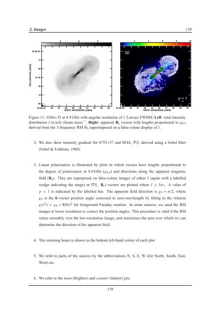
Figure 11: 0206+35 at 4.9 GHz with angular resolution of 1.2 arcsec FWHM. Left: total intensity<br />
<strong>di</strong>stribution I in mJy (beam area) −1 . Right: apparent B a vectors with lengths proportional to p 4.9<br />
derived from the 3-frequency RM fit, superimposed on a false-colour <strong>di</strong>splay of I.<br />
2. We also show intensity gra<strong>di</strong>ent for 0755+37 and M 84,|∇I|, derived using a Sobel filter<br />
(Sobel & Feldman, 1968).<br />
3. Linear polarization is illustrated by plots in which vectors have lengths proportional to<br />
the degree of polarization at 4.9 GHz (p 4.9 ) and <strong>di</strong>rections along the apparent magnetic<br />
field (B a ). They are superposed on false-colour images of either I (again with a labelled<br />
wedge in<strong>di</strong>cating the range) or|∇I|. B a ) vectors are plotted where I ≥ 5σ I . A value of<br />
p = 1 is in<strong>di</strong>cated by the labelled bar. The apparent field <strong>di</strong>rection isχ 0 +π/2, where<br />
χ 0 is the E-vector position angle corrected to zero-wavelength by fitting to the relation<br />
χ(λ 2 )=χ 0 + RMλ 2 for foreground Faraday rotation. In some sources, we used the RM<br />
images at lower resolution to correct the position angles. This procedure is valid if the RM<br />
varies smoothly over the low-resolution image, and maximises the area over which we can<br />
determine the <strong>di</strong>rection of the apparent field.<br />
4. The restoring beam is shown in the bottom left-hand corner of each plot.<br />
5. We refer to parts of the sources by the abbreviations N, S, E, W (for North, South, East,<br />
West) etc.<br />
6. We refer to the main (brighter) and counter (fainter) jets.<br />
139