Proceedings 2002/2003 - IRSE
Proceedings 2002/2003 - IRSE
Proceedings 2002/2003 - IRSE

Create successful ePaper yourself
Turn your PDF publications into a flip-book with our unique Google optimized e-Paper software.
EUROBALISE TRANSMISSION SYSTEM, A TECHNICAL OVERVIEW 27<br />
In general, the detailed specification of the balise<br />
is very rigid leaving a minimum of flexibility, whilst<br />
the specification of the on-board transmission<br />
equipment is fairly flexible in order to allow various<br />
alternatives for on-board optimisation.<br />
4.2 EUROBALISE<br />
A Eurobalise is interrogated and tele-powered by<br />
an inductively coupled tele-powering signal. The<br />
response of the Eurobalise is also an inductively<br />
coupled up-link signal. Source and sink of the<br />
tele-powering signal and the up-link signal respectively<br />
is the vehicle mounted antenna unit.<br />
Figure 3 – Eurobalise and its Main Interfaces<br />
The origin of the data carried by the up-link signal<br />
is a non-volatile memory in a fixed Eurobalise, or a<br />
serial data-link (the balise control interface) in a<br />
controlled Eurobalise. The data in the non-volatile<br />
memory is programmed on installation of the<br />
Eurobalise. If the Balise Controlling Interface is<br />
disturbed or interrupted, a controlled Eurobalise<br />
automatically switches over to transmitting the<br />
telegram in its internal non-volatile memory (which is<br />
also fitted in controlled Eurobalises).<br />
The Lineside Electronic Unit (LEU) receives<br />
messages from the wayside signalling or the interlocking.<br />
They are converted into Eurobalise<br />
telegrams (fulfilling the requirements of the telegram<br />
format), and are passed through the balise control<br />
interface to the Eurobalise, which transmits them to<br />
the on-board transmission equipment on passing<br />
trains.<br />
The Eurobalise generates a field that is picked up<br />
by the on-board antenna unit. Current flowing in the<br />
transmitting loop in the Eurobalise induces a voltage<br />
in the reception loop in the antenna unit.<br />
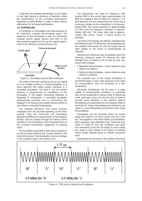
Two frequencies are used for frequency shift<br />
keying (FSK) of the up-link data, approximately 3.9<br />
MHz for a logical 0 and 4.5 MHz for a logical 1. In a<br />
shift between the two frequencies the carrier has a<br />
continuous phase (ie the modulation is continuousphase<br />
FSK). The centre frequency is approximately<br />
4.2 MHz and the frequency deviation is approximately<br />
282 kHz. The mean data rate is approximately<br />
565 kbit/s. Figure 4 below shows an<br />
example.<br />
Two sizes of Eurobalise are defined, Standard size<br />
and Reduced size. The Reduced size Eurobalise can<br />
be installed transversely (ie with its longer side at<br />
right angles to the track) or longitudinally as<br />
required.<br />
Standard and Reduced size Eurobalises have the<br />
following reference areas for defining the field<br />
strength from an antenna unit as well as their own<br />
output field strength:<br />
• Standard size Eurobalise – active reference area<br />
358mm by 488mm;<br />
• Reduced size Eurobalise – active reference area<br />
200mm by 390mm.<br />
The physical size of the actual Eurobalise is<br />
somewhat larger in each case because of the need<br />
for encapsulation, and the thickness is a few<br />
centimetres.<br />
Obviously, Eurobalises will be used in a large<br />
variety of environmental conditions. In particular<br />
they will be subjected to various kinds of débris (eg<br />
water, salt water, snow, ice, iron ore, etc). In order to<br />
provide some flexibility in this specific respect<br />
Eurobalises are subdivided into two classes, Class A<br />
and Class B. Class A Eurobalises are intended to be<br />
used in a more demanding environment than Class<br />
B Eurobalises.<br />
Eurobalises can be mounted within an overall<br />
range from 93mm to 210mm below the top of the<br />
rail. This applies to the entire family of Eurobalises.<br />
Each separate type (Standard size, Reduced size,<br />
Class A, Class B, etc) has limitations and does<br />
not necessarily cover the full range. In some cases<br />
the range is also limited if the balise is installed<br />
where certain defined types of metallic structures<br />
exist.<br />
Eurobalises are mounted in the middle of the track<br />
Figure 4 – FSK Up-link Signal from Eurobalise