Proceedings 2002/2003 - IRSE
Proceedings 2002/2003 - IRSE
Proceedings 2002/2003 - IRSE

Create successful ePaper yourself
Turn your PDF publications into a flip-book with our unique Google optimized e-Paper software.
EURORADIO AND THE RBC 33<br />
another while maintaining their normal operation in<br />
ERTMS Level 2.<br />
To ensure safe communication between the<br />
trackside signalling system and the train whilst<br />
maintaining operational efficiency requires that the<br />
RBC is based on a high integrity architecture that<br />
can tolerate failures. When in normal operation, the<br />
RBC sends to each of the trains with which it<br />
communicates in its area of control movement<br />
authority information, together with route<br />
geographic information that the train must observe<br />
in calculating a safe speed. The train sends<br />
information about its location to the RBC to enable<br />
calculation of appropriate movement authority<br />
parameters by the RBC. Communication between<br />
the RBC and the train is therefore bi-directional via<br />
the mandated GSM-R communications network,<br />
using the protocol defined later in this paper.<br />
The regulation and traffic control system (CTC or<br />
Local Control) sends requests for route<br />
establishment to the interlockings. The interlockings<br />
set up and lock the routes requested by the<br />
CTC/Local Control, and send the information that<br />
the route is set up and locked to the RBC. When the<br />
RBC undertakes control of a train that requires to<br />
use a route, it checks that the interlocking has<br />
reserved that route for that train before sending the<br />
movement authority for the train to use it. Once the<br />
train has entered the route, or in the event that the<br />
train does not use the route, the RBC and the<br />
interlocking co-operate to release the route, so as to<br />
ensure the consistency of the information managed<br />
by the RBC and by the interlocking. The CTC/Local<br />
Control retains its current functions of requesting<br />
route establishment. The interlocking retains its<br />
current functions, together with the additional<br />
functions of proceed and approach locking release<br />
to the RBC.<br />
For the ERTMS Level 2 system, the train’s location<br />
is mainly determined by means of axle counters or<br />
track circuit occupancy. The interlocking detects<br />
track occupancy and sends this information to the<br />
RBC. The RBC uses this track occupancy information<br />
to determine the movement authority limit for<br />
the train (regardless of whether the train ahead is<br />
under its control). The location information sent by<br />
the train to the RBC is used for various functions,<br />
such as: association of track circuit occupancy with<br />
the train; determination of the point where the<br />
geographic information associated with the<br />
movement authority begins; and diverse checking of<br />
the train’s location once the routes are released.<br />
When a train is approaching the boundary between<br />
two RBCs, the RBCs start to communicate with<br />
each other so that the movement authority can be<br />
extended across the boundary. As the train is<br />
crossing the boundary, control passes from the<br />
“Handover RBC” to the “Accepting RBC”.<br />
3 INTRODUCTION TO EURORADIO<br />
The choice of GSM for the radio bearer network<br />
was made some years ago, and work progressed in<br />
the EIRENE project to specify the additional<br />
requirements for railways. The MORANE project was<br />
given responsibility for the detailed specifications<br />
and for demonstrating the suitability of GSM-R (ie<br />
GSM for Railways). However, because of the<br />
complexity of a modern digital radio system, it is<br />
impossible to guarantee safe transmission, or even,<br />
in general, that it cannot be hacked into. It was<br />
therefore necessary to define an additional module<br />
between the application and the bearer that would<br />
be responsible for the safe transmission of data<br />
across the radio network – this was EuroRadio.<br />
Specifications for EuroRadio have been available<br />
for about seven years, written by various groups and<br />
in various stages of release. The specifications have<br />
always assumed concept implementation on<br />
GSM-R, which is regarded as an Open Transmission<br />
System as defined by CENELEC prEN50159-2. It<br />
must be remembered that the specifications are only<br />
concerned with interoperability, not with defining a<br />
complete system, although they are limited to a<br />
circuit switched network. Even so, there is scope for<br />
a number of different implementations where<br />
interoperability is unaffected – this particularly<br />
affects functions that are local to one end of the link.<br />
In this paper, a typical implementation is described,<br />
but it is not necessarily the only one possible.<br />
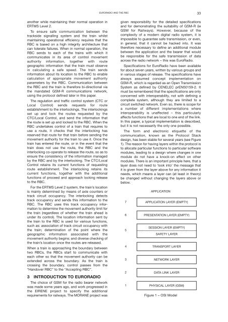
The form and electronic etiquette of the<br />
communication, known as the Protocol Stack<br />
design, has been stable for several years (see Figure<br />
1). The reason for having layers within the protocol is<br />
to allocate particular functions to particular software<br />
modules, leading to a design where changes in one<br />
module do not have a knock-on effect on other<br />
modules. There is an important principle here, that a<br />
layer does not need to ‘look into’ the message that<br />
it is given from the layer above for any information it<br />
needs, which means a layer can (at least in theory)<br />
be changed without changing the layers above or<br />
below.<br />
7<br />
6<br />
5<br />
4<br />
3<br />
2<br />
1<br />
APPLICATION<br />
APPLICATION LAYER (EMPTY)<br />
PRESENTATION LAYER (EMPTY)<br />
SESSION LAYER (EMPTY)<br />
SAFETY LAYER<br />
TRANSPORT LAYER<br />
NETWORK LAYER<br />
DATA LINK LAYER<br />
PHYSICAL LAYER (GSM)<br />
Figure 1 – OSI Model