Proceedings 2002/2003 - IRSE
Proceedings 2002/2003 - IRSE
Proceedings 2002/2003 - IRSE

Create successful ePaper yourself
Turn your PDF publications into a flip-book with our unique Google optimized e-Paper software.
SIGNALLING CONTROL CENTRES TODAY AND TOMORROW 59<br />
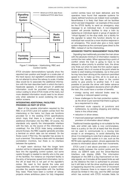
Signalling<br />
Control<br />
System<br />
Interlocking<br />
Trackside<br />
signalling<br />
Minimum ETCS data flows<br />
Additional ETCS data flows<br />
Radio<br />
Block<br />
Centre<br />
Trains<br />
Figure 7: Interfaces – Interlocking, RBC and<br />
Control Centre<br />
ETCS simulator demonstrations typically show the<br />
reported train position and length on a scale plan of<br />
the track layout, but signaller’s workstation screens<br />
do not attempt to show the railway to scale. A better<br />
idea would be to associate the additional information<br />
with the train describer berth in which the train’s<br />
headcode appears. A small amount of additional<br />
information could be provided continuously (eg<br />
colour coding to show ETCS mode of the train), but<br />
more detailed information would need to be shown<br />
only when selected to avoid cluttering the workstation<br />
screens.<br />
INTEGRATING ADDITIONAL FACILITIES<br />
PROVIDED AS PART OF ETCS<br />
Most of the variable information required by the<br />
RBC in an ETCS Level 2/3 system comes from the<br />
interlocking or the trains, but there are functions<br />
provided for in the existing ETCS specifications<br />
which imply that there is a means of entering<br />
additional information into the RBC. Of course, the<br />
standards only specify the interoperable interface<br />
with the train, so the source of this information is<br />
undefined. For the ETCS trials being undertaken<br />
around Europe, the RBC supplier generally provides<br />
a terminal on which data can be entered. On the<br />
Swiss Level 2 Pilot line, the signaller has access to<br />
such a terminal. This shares a desk with his standard<br />
workstation monitors, but there is no interface<br />
between the systems.<br />
It might seem obvious that the longer term<br />
solution will be to integrate the additional RBC interface<br />
into the signalling control system, but some<br />
careful thought is needed to identify who is the user<br />
of the facilities. For instance an important facility is<br />
the entry of temporary speed limit information, but in<br />
the UK at least this is not part of the signaller’s<br />
duties. We need to first decide the rules and<br />
responsibilities, and then engineer a system which<br />
provides the people responsible with the facilities<br />
they need. There have been a number of railway<br />
projects where ambitious plans for fully integrated<br />
control centres have not been delivered, and the<br />
operators have found that separate systems for<br />
clearly defined functions are indeed more workable.<br />
Nevertheless it is likely that there will be facilities<br />
which are best integrated – an example of this would<br />
be the ETCS facility to send an emergency stop<br />
message to an individual train. A non-integrated<br />
system will provide facilities to stop a train by<br />
replacing an individual signal or group of signals (or<br />
“virtual signals”) to the stop state, but a facility for<br />
the signaller to select this function directly for an<br />
individual train would be a more intuitive response in<br />
an emergency. This would also give a more rapid<br />
system response as the command goes direct to the<br />
RBC, instead of via the interlocking.<br />
ADVANCED TRAFFIC MANAGEMENT FACILITIES<br />
Signalling has traditionally provided the train driver<br />
with the absolute minimum of information needed to<br />
control the train safely. When approaching a point of<br />
conflict where the train is going to have to be<br />
delayed to allow priority to another train, the driver<br />
only finds out when he sees the first caution signal.<br />
At line speed, this is of course at the point where he<br />
needs to start braking immediately. Up to that point<br />
he may have been driving at the maximum permitted<br />
speed to try to make up time, all to no avail as a<br />
decision has already been taken in the control<br />
centre to give priority to another train. If it was<br />
possible to provide the driver with better advance<br />
warning of train regulation decisions which will affect<br />
the train, this could have a number of benefits:<br />
• energy saving and reduced brake wear by<br />
coasting or reduced speed running;<br />
• fewer challenges to the train protection system,<br />
as the driver is pre-warned that there is going to<br />
be a requirement to stop;<br />
• optimised route capacity at junctions and<br />
bottlenecks, by avoiding stopping and starting<br />
trains in the critical area;<br />
• reduction in driver stress;<br />
• improved passenger satisfaction, through better<br />
provision of information about delays.<br />
Traditional lineside signalling is not suitable for this<br />
task, and whilst cab radio is now commonplace,<br />
there is a policy (in the UK at least) that this should<br />
not be used to communicate to a moving train<br />
except in an emergency, to avoid distracting the<br />
driver. It is interesting to note that in places where an<br />
“open channel” radio system is in use, such as the<br />
RETB radio signalling system, drivers appreciate the<br />
access to information about other train movements.<br />
ETCS Level 2 and above provides a communications<br />
facility between the control centre and the<br />
driver, via GSM-R radio and the Driver-Machine<br />
Interface cab display (DMI). The information<br />
displayed on the DMI is a big improvement on lineside<br />
signals, as it includes all the speed limits as well<br />
as the distance the train is authorised to proceed,<br />
but it still fails to tell the driver anything about what<br />
is happening beyond the current limit of movement<br />
authority. However, there is no reason why the DMI<br />
should be limited in this way, and the DMI concept<br />
which has evolved with ETCS includes fields for