Proceedings 2002/2003 - IRSE
Proceedings 2002/2003 - IRSE
Proceedings 2002/2003 - IRSE

Create successful ePaper yourself
Turn your PDF publications into a flip-book with our unique Google optimized e-Paper software.
EUROCAB AND THE DRIVER MMI – AN INTRODUCTION TO THE TECHNOLOGY 45<br />
Eurobalise and Euroloop (optional) transmission<br />
module functionality is included. The DMI is<br />
connected via MVB.<br />
This system can be easily upgraded by a<br />
Euroradio module (via serial connection) in a second<br />
rack. Ample space is available in this to integrate<br />
peripheral modules such as GSM-R mobile or a<br />
juridical recorder, which is not available in the EVC.<br />
DRIVER MACHINE INTERFACES<br />
DMIs are displays mounted in the driver’s desk.<br />
They are available from several suppliers, such as<br />
Deuta and Pixy. For ERTMS/ETCS suppliers, these<br />
modules are normally peripheral units which will be<br />
connected to the EVC by the communications bus<br />
(MVB in the case of Siemens ERTMS/ETCS<br />
equipment).<br />
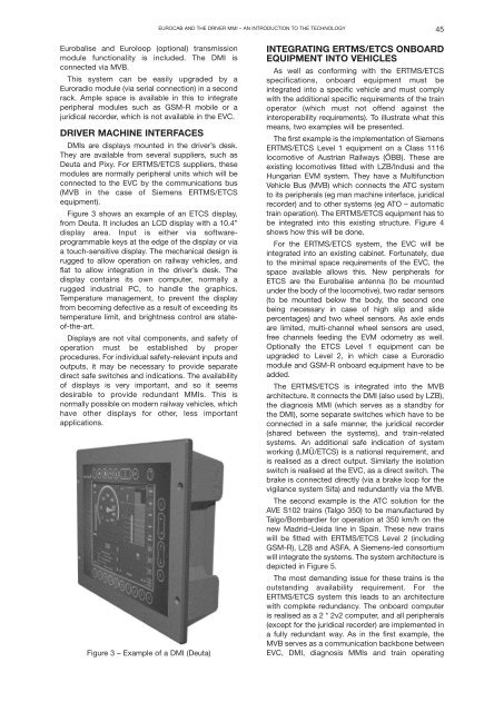
Figure 3 shows an example of an ETCS display,<br />
from Deuta. It includes an LCD display with a 10.4”<br />
display area. Input is either via softwareprogrammable<br />
keys at the edge of the display or via<br />
a touch-sensitive display. The mechanical design is<br />
rugged to allow operation on railway vehicles, and<br />
flat to allow integration in the driver’s desk. The<br />
display contains its own computer, normally a<br />
rugged industrial PC, to handle the graphics.<br />
Temperature management, to prevent the display<br />
from becoming defective as a result of exceeding its<br />
temperature limit, and brightness control are stateof-the-art.<br />
Displays are not vital components, and safety of<br />
operation must be established by proper<br />
procedures. For individual safety-relevant inputs and<br />
outputs, it may be necessary to provide separate<br />
direct safe switches and indications. The availability<br />
of displays is very important, and so it seems<br />
desirable to provide redundant MMIs. This is<br />
normally possible on modern railway vehicles, which<br />
have other displays for other, less important<br />
applications.<br />
Figure 3 – Example of a DMI (Deuta)<br />
INTEGRATING ERTMS/ETCS ONBOARD<br />
EQUIPMENT INTO VEHICLES<br />
As well as conforming with the ERTMS/ETCS<br />
specifications, onboard equipment must be<br />
integrated into a specific vehicle and must comply<br />
with the additional specific requirements of the train<br />
operator (which must not offend against the<br />
interoperability requirements). To illustrate what this<br />
means, two examples will be presented.<br />
The first example is the implementation of Siemens<br />
ERTMS/ETCS Level 1 equipment on a Class 1116<br />
locomotive of Austrian Railways (ÖBB). These are<br />
existing locomotives fitted with LZB/Indusi and the<br />
Hungarian EVM system. They have a Multifunction<br />
Vehicle Bus (MVB) which connects the ATC system<br />
to its peripherals (eg man machine interface, juridical<br />
recorder) and to other systems (eg ATO – automatic<br />
train operation). The ERTMS/ETCS equipment has to<br />
be integrated into this existing structure. Figure 4<br />
shows how this will be done.<br />
For the ERTMS/ETCS system, the EVC will be<br />
integrated into an existing cabinet. Fortunately, due<br />
to the minimal space requirements of the EVC, the<br />
space available allows this. New peripherals for<br />
ETCS are the Eurobalise antenna (to be mounted<br />
under the body of the locomotive), two radar sensors<br />
(to be mounted below the body, the second one<br />
being necessary in case of high slip and slide<br />
percentages) and two wheel sensors. As axle ends<br />
are limited, multi-channel wheel sensors are used,<br />
free channels feeding the EVM odometry as well.<br />
Optionally the ETCS Level 1 equipment can be<br />
upgraded to Level 2, in which case a Euroradio<br />
module and GSM-R onboard equipment have to be<br />
added.<br />
The ERTMS/ETCS is integrated into the MVB<br />
architecture. It connects the DMI (also used by LZB),<br />
the diagnosis MMI (which serves as a standby for<br />
the DMI), some separate switches which have to be<br />
connected in a safe manner, the juridical recorder<br />
(shared between the systems), and train-related<br />
systems. An additional safe indication of system<br />
working (LMÜ/ETCS) is a national requirement, and<br />
is realised as a direct output. Similarly the isolation<br />
switch is realised at the EVC, as a direct switch. The<br />
brake is connected directly (via a brake loop for the<br />
vigilance system Sifa) and redundantly via the MVB.<br />
The second example is the ATC solution for the<br />
AVE S102 trains (Talgo 350) to be manufactured by<br />
Talgo/Bombardier for operation at 350 km/h on the<br />
new Madrid–Lleida line in Spain. These new trains<br />
will be fitted with ERTMS/ETCS Level 2 (including<br />
GSM-R), LZB and ASFA. A Siemens-led consortium<br />
will integrate the systems. The system architecture is<br />
depicted in Figure 5.<br />
The most demanding issue for these trains is the<br />
outstanding availability requirement. For the<br />
ERTMS/ETCS system this leads to an architecture<br />
with complete redundancy. The onboard computer<br />
is realised as a 2 * 2v2 computer, and all peripherals<br />
(except for the juridical recorder) are implemented in<br />
a fully redundant way. As in the first example, the<br />
MVB serves as a communication backbone between<br />
EVC, DMI, diagnosis MMIs and train operating