Proceedings 2002/2003 - IRSE
Proceedings 2002/2003 - IRSE
Proceedings 2002/2003 - IRSE

You also want an ePaper? Increase the reach of your titles
YUMPU automatically turns print PDFs into web optimized ePapers that Google loves.
56<br />
SIGNALLING CONTROL CENTRES TODAY AND TOMORROW<br />
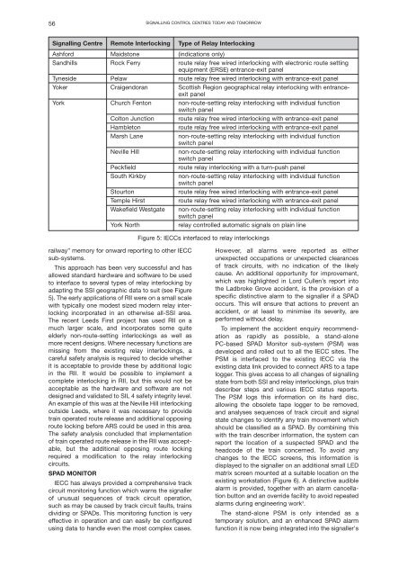
Signalling Centre Remote Interlocking Type of Relay Interlocking<br />
Ashford Maidstone (indications only)<br />
Sandhills Rock Ferry route relay free wired interlocking with electronic route setting<br />
equipment (ERSE) entrance-exit panel<br />
Tyneside Pelaw route relay free wired interlocking with entrance-exit panel<br />
Yoker Craigendoran Scottish Region geographical relay interlocking with entranceexit<br />
panel<br />
York Church Fenton non-route-setting relay interlocking with individual function<br />
switch panel<br />
Colton Junction route relay free wired interlocking with entrance-exit panel<br />
Hambleton<br />
route relay free wired interlocking with entrance-exit panel<br />
Marsh Lane<br />
non-route-setting relay interlocking with individual function<br />
switch panel<br />
Neville Hill<br />
non-route-setting relay interlocking with individual function<br />
switch panel<br />
Peckfield<br />
route relay interlocking with a turn-push panel<br />
South Kirkby<br />
non-route-setting relay interlocking with individual function<br />
switch panel<br />
Stourton<br />
route relay free wired interlocking with entrance-exit panel<br />
Temple Hirst<br />
route relay free wired interlocking with entrance-exit panel<br />
Wakefield Westgate non-route-setting relay interlocking with individual function<br />
switch panel<br />
York North<br />
relay controlled automatic signals on plain line<br />
Figure 5: IECCs interfaced to relay interlockings<br />
railway” memory for onward reporting to other IECC<br />
sub-systems.<br />
This approach has been very successful and has<br />
allowed standard hardware and software to be used<br />
to interface to several types of relay interlocking by<br />
adapting the SSI geographic data to suit (see Figure<br />
5). The early applications of RII were on a small scale<br />
with typically one modest sized modern relay interlocking<br />
incorporated in an otherwise all-SSI area.<br />
The recent Leeds First project has used RII on a<br />
much larger scale, and incorporates some quite<br />
elderly non-route-setting interlockings as well as<br />
more recent designs. Where necessary functions are<br />
missing from the existing relay interlockings, a<br />
careful safety analysis is required to decide whether<br />
it is acceptable to provide these by additional logic<br />
in the RII. It would be possible to implement a<br />
complete interlocking in RII, but this would not be<br />
acceptable as the hardware and software are not<br />
designed and validated to SIL 4 safety integrity level.<br />
An example of this was at the Neville Hill interlocking<br />
outside Leeds, where it was necessary to provide<br />
train operated route release and additional opposing<br />
route locking before ARS could be used in this area.<br />
The safety analysis concluded that implementation<br />
of train operated route release in the RII was acceptable,<br />
but the additional opposing route locking<br />
required a modification to the relay interlocking<br />
circuits.<br />
SPAD MONITOR<br />
IECC has always provided a comprehensive track<br />
circuit monitoring function which warns the signaller<br />
of unusual sequences of track circuit operation,<br />
such as may be caused by track circuit faults, trains<br />
dividing or SPADs. This monitoring function is very<br />
effective in operation and can easily be configured<br />
using data to handle even the most complex cases.<br />
However, all alarms were reported as either<br />
unexpected occupations or unexpected clearances<br />
of track circuits, with no indication of the likely<br />
cause. An additional opportunity for improvement,<br />
which was highlighted in Lord Cullen’s report into<br />
the Ladbroke Grove accident, is the provision of a<br />
specific distinctive alarm to the signaller if a SPAD<br />
occurs. This will ensure that actions to prevent an<br />
accident, or at least to minimise its severity, are<br />
performed without delay.<br />
To implement the accident enquiry recommendation<br />
as rapidly as possible, a stand-alone<br />
PC-based SPAD Monitor sub-system (PSM) was<br />
developed and rolled out to all the IECC sites. The<br />
PSM is interfaced to the existing IECC via the<br />
existing data link provided to connect ARS to a tape<br />
logger. This gives access to all changes of signalling<br />
state from both SSI and relay interlockings, plus train<br />
describer steps and various IECC status reports.<br />
The PSM logs this information on its hard disc,<br />
allowing the obsolete tape logger to be removed,<br />
and analyses sequences of track circuit and signal<br />
state changes to identify any train movement which<br />
should be classified as a SPAD. By combining this<br />
with the train describer information, the system can<br />
report the location of a suspected SPAD and the<br />
headcode of the train concerned. To avoid any<br />
changes to the IECC screens, this information is<br />
displayed to the signaller on an additional small LED<br />
matrix screen mounted at a suitable location on the<br />
existing workstation (Figure 6). A distinctive audible<br />
alarm is provided, together with an alarm cancellation<br />
button and an override facility to avoid repeated<br />
alarms during engineering work 3 .<br />
The stand-alone PSM is only intended as a<br />
temporary solution, and an enhanced SPAD alarm<br />
function it is now being integrated into the signaller's