Proceedings 2002/2003 - IRSE
Proceedings 2002/2003 - IRSE
Proceedings 2002/2003 - IRSE

Create successful ePaper yourself
Turn your PDF publications into a flip-book with our unique Google optimized e-Paper software.
44<br />
EUROCAB AND THE DRIVER MMI – AN INTRODUCTION TO THE TECHNOLOGY<br />
STM<br />
National<br />
System<br />
FFFIS<br />
Train<br />
FIS<br />
TIU<br />
EUROBALIKE EUROLOOP EURO-<br />
RADIO<br />
Radio<br />
infill unit<br />
FFFIS (FFFIS) (FIS)<br />
Interlocking<br />
and LEU<br />
Control Centre<br />
Kernel<br />
MMI<br />
BTM LTM EURORADIO<br />
FFFIS<br />
FFFIS<br />
Driver<br />
FIS<br />
Jur.<br />
ETCS Recording<br />
Onboard<br />
FIS<br />
FFFIS<br />
GSM-<br />
Mobile<br />
GSMfixed<br />
network<br />
EURORADIO<br />
RBC 1<br />
FIS<br />
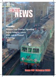
Figure 1 – ERTMS/ETCS System Architecture<br />
• Juridical Recording Downloading Tool –<br />
interface for authorities to download stored<br />
information.<br />
• STM (Specific Transmission Module) – interface<br />
to modules of heritage systems.<br />
• Eurobalise (BTM – Balise Transmission System)<br />
air gap interface.<br />
• Euroloop (LTM – Loop Transmission Module) air<br />
gap interface.<br />
• Euroradio interface to the GSM-R mobile.<br />
The TIU and the DMI interface are only specified<br />
as functional interfaces, ie it is up to the<br />
manufacturer to design the physical interface as<br />
long as the logical requirements are met.<br />
As already mentioned, a set of informative<br />
documents exists for the DMI, specifying the<br />
ergonomic interface between the ERTMS/ETCS<br />
onboard subsystem and the driver (see Table 1).<br />
Although they are not prescribed in law, they are<br />
often seen as quasi-standards. Created by<br />
CENELEC Working Group WGA9D, these<br />
documents specify the ergonomic arrangement of<br />
the information on the DMI display, the symbols<br />
used, the audible information and the data entry<br />
procedure.<br />
FIS<br />
JRU<br />
Downloading<br />
Tool<br />
FFFIS<br />
Odometry<br />
FIS<br />
RBC 2<br />
ETCS Trackside<br />
FIS<br />
FIS<br />
Key<br />
Management<br />
Centre<br />
Besides specifying the system architecture, the<br />
SRS also describes the functionality of the system.<br />
The functionality, the details of which will not be<br />
described here, is roughly comparable to high-end<br />
ATC systems like the German system LZB 80. It is<br />
scalable from an overlay spot transmission system<br />
(ETCS Level 1), via a continuous transmission<br />
system (Level 2) to a sophisticated stand-alone<br />
system (Level 3). Compared to older systems, the<br />
onboard system includes more functionality, eg<br />
calculation of braking curves and other<br />
performance-demanding features.<br />
THE SIEMENS SOLUTION FOR AN ETCS<br />
SUBSYSTEM<br />
On the basis of the above-mentioned<br />
specifications Siemens has developed an ERTMS/<br />
ETCS onboard equipment. It consists of a European<br />
Vital Computer (EVC) which can be integrated in the<br />
most flexible way into a vehicle, and which can<br />
utilise peripherals such as wheel sensors, DMIs,<br />
radar sensors etc in a similarly flexible way. The goal<br />
was to develop an EVC with minimum space<br />
requirements integrating as much functionality as<br />
possible (eg Eurobalise BTM functionality, option to<br />
integrate Euroloop functionality and STM interface).<br />
The onboard equipment will be simply upgradeable<br />
to Level 2, and will be fully-compliant with the<br />
specifications mentioned above.<br />
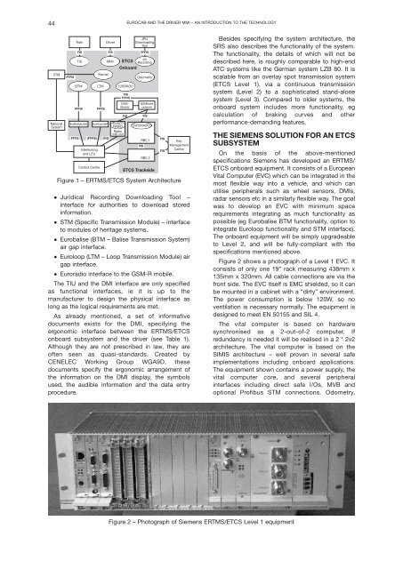
Figure 2 shows a photograph of a Level 1 EVC. It<br />
consists of only one 19” rack measuring 438mm x<br />
135mm x 320mm. All cable connections are via the<br />
front side. The EVC itself is EMC shielded, so it can<br />
be mounted in a cabinet with a “dirty” environment.<br />
The power consumption is below 120W, so no<br />
ventilation is necessary normally. The equipment is<br />
designed to meet EN 50155 and SIL 4.<br />
The vital computer is based on hardware<br />
synchronised as a 2-out-of-2 computer. If<br />
redundancy is needed it will be realised in a 2 * 2v2<br />
architecture. The vital computer is based on the<br />
SIMIS architecture – well proven in several safe<br />
implementations including onboard applications.<br />
The equipment shown contains a power supply, the<br />
vital computer core, and several peripheral<br />
interfaces including direct safe I/Os, MVB and<br />
optional Profibus STM connections. Odometry,<br />
Figure 2 – Photograph of Siemens ERTMS/ETCS Level 1 equipment