Proceedings 2002/2003 - IRSE
Proceedings 2002/2003 - IRSE
Proceedings 2002/2003 - IRSE

Create successful ePaper yourself
Turn your PDF publications into a flip-book with our unique Google optimized e-Paper software.
CTRL SIGNALLING AND COMMUNICATIONS 75<br />
TECHNICAL DESCRIPTION<br />
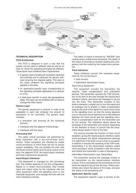
ITCS Architecture<br />
The ITCS is designed in such a way that the<br />
system can be used on different sites as well as on<br />
lines for which the signalling principles are different.<br />
Three layers have therefore been implemented:<br />
• A generic layer including all necessary hardware<br />
and software and in particular the generic software<br />
ensuring the required safety. This layer is<br />
the same whatever the signalling principles<br />
applied or the sites.<br />
• An application-specific layer corresponding to<br />
the signalling principles applicable to a network<br />
or a line.<br />
• A data layer specific to each site (geographical<br />
data). This layer can be modified with no need to<br />
change the other layers.<br />
Generic Layer<br />
The generic equipment is modular in order to be<br />
adaptable to each site whatever the amount of<br />
equipment to be controlled. The generic layer<br />
includes:<br />
• a processor unit ensuring all the functional<br />
process;<br />
• interfaces with the adjacent interlockings;<br />
• interfaces with the track.<br />
Processing Unit<br />
The safety critical processes are performed by<br />
three computers with a two-out-of-three architecture.<br />
These computers are checked by coded<br />
mono-processors of which there are two to ensure<br />
system availability. This unit handles the links with<br />
the Route Control Centre and the local control unit (if<br />
any), the adjacent ITCS, the input/output interfaces<br />
and local maintenance equipment.<br />
Input/Output Interfaces<br />
This equipment is managed by the processing<br />
unit. The number depends on the site configuration.<br />
Based on a coded mono-processor, they include<br />
input and output racks for the interfaces with the<br />
other equipment within the signalling room or the<br />
trackside equipment, and manage the links with the<br />
track interfaces cubicles.<br />
The safety of inputs is ensured by “SACEM” type<br />
coding using a coded mono-processor. The safety of<br />
the output is ensured by recreate-reading and comparison<br />
with the control by the coded mono-processor.<br />
Track Interfaces<br />
These interfaces concern the necessary equipment<br />
for the functioning of:<br />
• track circuits;<br />
• intermittent transmission loops.<br />
Track Circuit Equipment<br />
This equipment includes the transmitter, the<br />
receiver, cable compensation and orientation<br />
devices. The transmitter receives the TVM information<br />
to be sent to the train through the input/output<br />
interface cubicle, and forms the message to be put<br />
into the track. This transmitter consists of two<br />
distinct elements, a digital one to form the signal and<br />
an analogue one to amplify it. Cable compensation<br />
reduces the level of the signal for a track circuit close<br />
to the signalling room, so that the tuning depends<br />
only on the track circuit itself and not on the distance<br />
between the track circuit and the signalling room.<br />
There is compensation both for the transmitter and<br />
for the receiver. The orientation device allows the<br />
exchange of the transmitter and receiver depending<br />
on the direction of travel, to ensure that the transmitter<br />
always feeds in front of the train.<br />
The receiver provides the function of track circuit<br />
reception, giving the inputs/outputs interface coded<br />
mono-processor the signal characteristics allowing<br />
it to determine if the track circuit is free or occupied.<br />
In addition it ensures the rereading of the TVM code,<br />
transmitting it to the input/output interface coded<br />
mono-processor which compares it with the control<br />
and inhibits the transmitter in case of discrepancy.<br />
Intermittent Transmission Loop Transmitters<br />
The transmitter receives the message number to<br />
be transmitted via the inputs/outputs interface<br />
cubicle. This is calculated by the processing unit and<br />
forms the signal to be put into the loop. These transmitters<br />
also check the status of the loops, and give<br />
this status to the processing unit.<br />
Application Specific Layer<br />
The Application Specific Layer is formed of ele-