Proceedings 2002/2003 - IRSE
Proceedings 2002/2003 - IRSE
Proceedings 2002/2003 - IRSE

You also want an ePaper? Increase the reach of your titles
YUMPU automatically turns print PDFs into web optimized ePapers that Google loves.
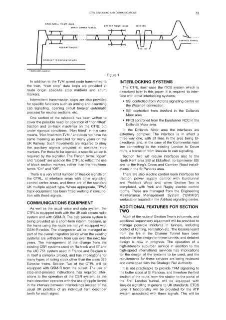
CTRL SIGNALLING AND COMMUNICATIONS 73<br />
Figure 1<br />
In addition to the TVM speed code transmitted to<br />
the train, “train stop” data loops are provided at<br />
route origin absolute stop markers and shunt<br />
markers.<br />
Intermittent transmission loops are also provided<br />
for specific functions such as arming and disarming<br />
cab signalling, opening circuit breaker (automatic<br />
process) for neutral sections, etc.<br />
One section of the rulebook has been written to<br />
cover the possible need for operation of “non fitted”<br />
traction and on-track machines on the CTRL but<br />
under rigorous conditions. “Non fitted” in this case<br />
means, "Not fitted with TVM," and does not have the<br />
same meaning as prevailed for many years on the<br />
UK Railway. Such movements are required to obey<br />
the auxiliary signals provided at absolute stop<br />
markers. For these to be opened, a specific action is<br />
required by the signaller. The French terms “open"<br />
and "closed” are used on the CTRL to reflect the use<br />
of block section markers, rather than the traditional<br />
terms “On" and "Off”.<br />
There is a very small number of lineside signals on<br />
the CTRL, at interface areas with other signalling<br />
control centre areas, and these are of the standard<br />
UK multiple aspect type. Where appropriate, TPWS<br />
track equipment has been fitted working in conjunction<br />
with these signals.<br />
COMMUNICATIONS EQUIPMENT<br />
As well as the usual voice and data system, the<br />
CTRL is equipped both with the UK cab secure radio<br />
system and with GSM-R. The cab secure system is<br />
being provided as a short-term interim measure, as<br />
the trains using the route are not yet equipped with<br />
GSM-R radios. The changeover will be managed as<br />
part of the overall migration policy when the existing<br />
systems are withdrawn from use over the next few<br />
years. The management of the change from the<br />
existing CSR systems used on Railtrack and ET and<br />
the UIC 751 system used in France and Belgium is<br />
in itself a complex project, and has implications for<br />
many types of rolling stock other than the class 373<br />
Eurostar trains. Section Two of the CTRL will be<br />
equipped with GSM-R from the outset. The use of<br />
stop-and-proceed instructions has required alterations<br />
to the operation of the CSR system, as the<br />
train describer operates with the use of ripple berths<br />
in the intervals between interlockings instead of the<br />
usual UK practice of an individual train describer<br />
berth for each signal.<br />
INTERLOCKING SYSTEMS<br />
The CTRL itself uses the ITCS system which is<br />
described later in this paper. It is required to interface<br />
with other interlocking systems:<br />
• SSI controlled from Victoria signalling centre on<br />
the Waterloo connection;<br />
• SSI controlled from Ashford in the Dollands<br />
Moor area;<br />
• PRCI controlled from the Eurotunnel RCC in the<br />
Dollands Moor area.<br />
In the Dollands Moor area the interfaces are<br />
extremely complex. The interface is in effect a<br />
three-way one, with all lines in the area being bidirectional<br />
and, in the case of the Continental main<br />
line connecting to the existing London to Dover<br />
route, a transition from lineside to cab signalling.<br />
Section Two will require interfaces also to the<br />
North Kent area SSI at Ebbsfleet, to Upminster SSI<br />
and to the King’s Cross and Camden Road installations<br />
in the St Pancras area.<br />
There are also electric control room interfaces for<br />
traction power supply control with Eurotunnel<br />
and Paddock Wood and, when Section Two is<br />
completed, with York and Rugby electric control<br />
rooms. These are managed from the Engineering<br />
Maintenance Management System (“EMMIS”)<br />
workstation located in the Ashford signalling centre.<br />
ADDITIONAL FEATURES FOR SECTION<br />
TWO<br />
Much of the route of Section Two is in tunnels, and<br />
additional supervisory equipment will be provided to<br />
manage possible incidents in tunnels, including<br />
control of lighting, ventilation etc. The lessons learnt<br />
from the fire in the Channel Tunnel have been<br />
included in the design for these tunnels, and detailed<br />
design is now in progress. The operation of a<br />
high-intensity suburban service in addition to the<br />
high-speed international services has implications<br />
for the design of the systems to be used, and the<br />
requirements for these services are being reviewed<br />
and developed with the Strategic Rail Authority.<br />
It is not practicable to provide TVM signalling to<br />
the buffer stops at St Pancras, and therefore the first<br />
section of the route, from the station to the portal of<br />
the first London tunnel, will be equipped with<br />
lineside signalling in general to UK standards. ETCS<br />
Level 1 functionality will be provided for the ATP<br />
system associated with these signals. This will be