Proceedings 2002/2003 - IRSE
Proceedings 2002/2003 - IRSE
Proceedings 2002/2003 - IRSE

Create successful ePaper yourself
Turn your PDF publications into a flip-book with our unique Google optimized e-Paper software.
78<br />
CTRL SIGNALLING AND COMMUNICATIONS<br />
APPLICATION FOR CTRL SECTION 1<br />
ARCHITECTURE<br />
Since the distance between two interlocking areas<br />
is about 10 km on CTRL, there is no need for an<br />
intermediate signalling room. The figure above<br />
shows the architecture of the signalling for CTRL<br />
Section 1.<br />
CAB SIGNALLING<br />
Block Sectioning Study<br />
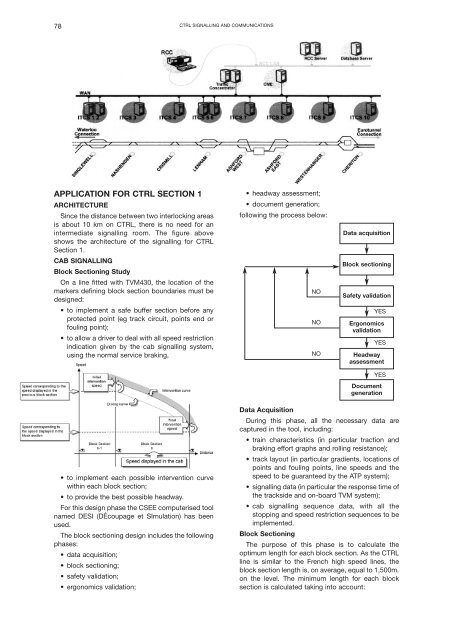
On a line fitted with TVM430, the location of the<br />
markers defining block section boundaries must be<br />
designed:<br />
• to implement a safe buffer section before any<br />
protected point (eg track circuit, points end or<br />
fouling point);<br />
• to allow a driver to deal with all speed restriction<br />
indication given by the cab signalling system,<br />
using the normal service braking,<br />
• headway assessment;<br />
• document generation;<br />
following the process below:<br />
NO<br />
NO<br />
NO<br />
Data acquisition<br />
Block sectioning<br />
Safety validation<br />
YES<br />
Ergonomics<br />
validation<br />
YES<br />
Headway<br />
assessment<br />
YES<br />
Document<br />
generation<br />
• to implement each possible intervention curve<br />
within each block section;<br />
• to provide the best possible headway.<br />
For this design phase the CSEE computerised tool<br />
named DESI (DÉcoupage et SImulation) has been<br />
used.<br />
The block sectioning design includes the following<br />
phases:<br />
• data acquisition;<br />
• block sectioning;<br />
• safety validation;<br />
• ergonomics validation;<br />
Data Acquisition<br />
During this phase, all the necessary data are<br />
captured in the tool, including:<br />
• train characteristics (in particular traction and<br />
braking effort graphs and rolling resistance);<br />
• track layout (in particular gradients, locations of<br />
points and fouling points, line speeds and the<br />
speed to be guaranteed by the ATP system);<br />
• signalling data (in particular the response time of<br />
the trackside and on-board TVM system);<br />
• cab signalling sequence data, with all the<br />
stopping and speed restriction sequences to be<br />
implemented.<br />
Block Sectioning<br />
The purpose of this phase is to calculate the<br />
optimum length for each block section. As the CTRL<br />
line is similar to the French high speed lines, the<br />
block section length is, on average, equal to 1,500m.<br />
on the level. The minimum length for each block<br />
section is calculated taking into account: