Proceedings 2002/2003 - IRSE
Proceedings 2002/2003 - IRSE
Proceedings 2002/2003 - IRSE

You also want an ePaper? Increase the reach of your titles
YUMPU automatically turns print PDFs into web optimized ePapers that Google loves.
SIGNALLING CONTROL CENTRES TODAY AND TOMORROW 55<br />
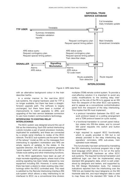
NATIONAL TRAIN<br />
SERVICE DATABASE<br />
Full timetables<br />
Daily timetable update<br />
TTP USER<br />
Timetable<br />
Summary timetables<br />
Timetable validation<br />
reports<br />
Request contingency plan<br />
Request special timing pattern<br />
TTP<br />
Main timetable<br />
Amendment timetable<br />
ARS status query<br />
Request contingency plan<br />
Request special timing pattern<br />
ARS status query<br />
Request contingency plan<br />
Request special timing pattern<br />
Train describer steps<br />
SIGNALLER<br />
Alarms<br />
ARS status<br />
Signalling<br />
Workstation<br />
Alarms<br />
ARS status<br />
TD code insert<br />
ARS<br />
Route availability<br />
Train detection<br />
Route request<br />
Figure 4: ARS data flows<br />
INTERLOCKING<br />
with an alternative background colour in the train<br />
describer berths.<br />
In a similar manner to the real-time IECC<br />
sub-systems, the original hardware used for TTP is<br />
no longer available, but there has been a straightforward<br />
upgrade path. The software is largely<br />
unchanged, but there have been a number of<br />
improvements to match upgrades to ARS, and<br />
upgrading of the train service database connection<br />
to use more modern communications technology.<br />
INTERFACING TO EXISTING RELAY<br />
INTERLOCKINGS<br />
The IECC system was designed around the use of<br />
SSI as the interlocking. Each SSI central interlocking<br />
cubicle includes a pair of panel processor modules,<br />
duplicated for availability, and these are connected<br />
by a simple serial interface to nodes of the IECC<br />
network. The IECC sub-systems use the same “state<br />
of the railway” model as SSI, so the messages from<br />
interlocking to signaller’s workstation and ARS are<br />
simply reports of updates to the states. In the<br />
opposite direction, the IECC sub-systems generate<br />
“panel requests” which are processed in the SSI to<br />
initiate route setting and other interlocking functions.<br />
All the IECC applications have been as part of<br />
major recreate-signalling projects, where most of the<br />
existing signalling has been totally replaced by new<br />
equipment including SSI. However, in some cases,<br />
there has been a desire to retain existing relay interlockings<br />
within the IECC controlled area. This need<br />
is satisfied by the Remote Interlocking Interface (RII)<br />
sub-system which allows a relay interlocking to be<br />
interfaced to IECC via a conventional time division<br />
multiplex (TDM) remote control system. To provide a<br />
cost-effective solution it is important to avoid any<br />
costly modifications to the existing relay interlocking,<br />
so the role of the RII is to appear as an SSI<br />
from the viewpoint of the other IECC sub-systems,<br />
and to appear as a conventional control/indication<br />
panel from the viewpoint of the relay interlocking.<br />
This implies that RII must implement:<br />
• a protocol translation (between the IECC network<br />
protocol based on a polling arrangement<br />
and a TDM protocol based on cyclic scans);<br />
• a functional translation to convert panel indication<br />
states into SSI-like states, and to convert<br />
SSI panel requests into switch and button<br />
sequences;<br />
• logic required to support IECC functionality<br />
which is usually provided in SSI but is not<br />
already provided in the relay interlocking (eg<br />
signallers’ reminders, ARS sub-areas, train<br />
operated route release).<br />
This functionality has been achieved by translating<br />
the SSI interlocking functional program into a high<br />
level language which allows it to run on the same<br />
Motorola 68000/VME hardware as other IECC<br />
sub-systems. The required functional translation and<br />
additional logic can then be implemented using<br />
standard SSI geographic data, which is well understood<br />
by designers and testers, and supported by<br />
the SSI Design Workstation tools. For instance<br />
indications reported from the interlocking over the<br />
TDM link are treated like input telegrams on the SSI<br />
trackside data link, and input telegram data is used<br />
to map these into the standard SSI “state of the