SVI-II Instruc Man.book - Fagerberg
SVI-II Instruc Man.book - Fagerberg
SVI-II Instruc Man.book - Fagerberg
You also want an ePaper? Increase the reach of your titles
YUMPU automatically turns print PDFs into web optimized ePapers that Google loves.
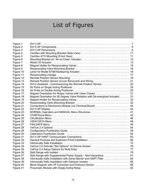
List of Figures<br />
Figure 1 <strong>SVI</strong> <strong>II</strong> AP. . . . . . . . . . . . . . . . . . . . . . . . . . . . . . . . . . . . . . . . . . . . . . . . . . . . . . . . . . . . . . 1<br />
Figure 2 <strong>SVI</strong> <strong>II</strong> AP Components . . . . . . . . . . . . . . . . . . . . . . . . . . . . . . . . . . . . . . . . . . . . . . . . . . . 5<br />
Figure 3 <strong>SVI</strong> <strong>II</strong> AP Dimensions. . . . . . . . . . . . . . . . . . . . . . . . . . . . . . . . . . . . . . . . . . . . . . . . . . . . 6<br />
Figure 4 Camflex with Mounting Bracket (Side View) . . . . . . . . . . . . . . . . . . . . . . . . . . . . . . . . . 11<br />
Figure 5 Camflex ATO Mounting (Front View) . . . . . . . . . . . . . . . . . . . . . . . . . . . . . . . . . . . . . . . 11<br />
Figure 6 Mounting Bracket on “Air-to-Close” Actuator . . . . . . . . . . . . . . . . . . . . . . . . . . . . . . . . . 12<br />
Figure 7 Model 33 Actuator . . . . . . . . . . . . . . . . . . . . . . . . . . . . . . . . . . . . . . . . . . . . . . . . . . . . . 13<br />
Figure 8 Magnet Holder for Reciprocating Valves . . . . . . . . . . . . . . . . . . . . . . . . . . . . . . . . . . . . 15<br />
Figure 9 Reciprocating Valve Mounting Bracket . . . . . . . . . . . . . . . . . . . . . . . . . . . . . . . . . . . . . 16<br />
Figure 10 Lever for Model 87/88 Multispring Actuator . . . . . . . . . . . . . . . . . . . . . . . . . . . . . . . . . . 16<br />
Figure 11 Reciprocating Linkage . . . . . . . . . . . . . . . . . . . . . . . . . . . . . . . . . . . . . . . . . . . . . . . . . . 17<br />
Figure 12 Remote Position Sensor Mounting. . . . . . . . . . . . . . . . . . . . . . . . . . . . . . . . . . . . . . . . . 19<br />
Figure 13 Remote Position Sensor (Cover Removed) and Wiring. . . . . . . . . . . . . . . . . . . . . . . . . 21<br />
Figure 14 <strong>SVI</strong>-<strong>II</strong> Assistant - Commissioning the Remote Position Sensor . . . . . . . . . . . . . . . . . . . 22<br />
Figure 15 Air Ports on Single Acting Positioner . . . . . . . . . . . . . . . . . . . . . . . . . . . . . . . . . . . . . . . 24<br />
Figure 16 Air Ports on Double Acting Positioner . . . . . . . . . . . . . . . . . . . . . . . . . . . . . . . . . . . . . . 25<br />
Figure 17 Magnet Orientation for Rotary Valves with Valve Closed . . . . . . . . . . . . . . . . . . . . . . . 31<br />
Figure 18 Magnet Orientation for 90 Degree Valve Rotation with De-energized Actuator. . . . . . . 31<br />
Figure 19 Magnet Holder for Reciprocating Valves . . . . . . . . . . . . . . . . . . . . . . . . . . . . . . . . . . . . 32<br />
Figure 20 Reciprocating Valve Mounting Bracket . . . . . . . . . . . . . . . . . . . . . . . . . . . . . . . . . . . . . 32<br />
Figure 21 Connections to Electronics Module (via Terminal Board) . . . . . . . . . . . . . . . . . . . . . . . 34<br />
Figure 22 <strong>SVI</strong> <strong>II</strong> AP Display . . . . . . . . . . . . . . . . . . . . . . . . . . . . . . . . . . . . . . . . . . . . . . . . . . . . . . 40<br />
Figure 23 NORMAL Operation and MANUAL Menu Structures. . . . . . . . . . . . . . . . . . . . . . . . . . . 41<br />
Figure 24 CONFIGure Menu . . . . . . . . . . . . . . . . . . . . . . . . . . . . . . . . . . . . . . . . . . . . . . . . . . . . . 42<br />
Figure 25 CALIBration Menu . . . . . . . . . . . . . . . . . . . . . . . . . . . . . . . . . . . . . . . . . . . . . . . . . . . . . 46<br />
Figure 26 VIEW DATA Menu . . . . . . . . . . . . . . . . . . . . . . . . . . . . . . . . . . . . . . . . . . . . . . . . . . . . . 48<br />
Figure 27 FAILSAFE Menu . . . . . . . . . . . . . . . . . . . . . . . . . . . . . . . . . . . . . . . . . . . . . . . . . . . . . . 49<br />
Figure 28 ValVue 2.4 Options . . . . . . . . . . . . . . . . . . . . . . . . . . . . . . . . . . . . . . . . . . . . . . . . . . . . 54<br />
Figure 29 Configuration Pushbutton Guide . . . . . . . . . . . . . . . . . . . . . . . . . . . . . . . . . . . . . . . . . . 59<br />
Figure 30 Calibration Pushbutton Guide . . . . . . . . . . . . . . . . . . . . . . . . . . . . . . . . . . . . . . . . . . . . 62<br />
Figure 31 <strong>SVI</strong> <strong>II</strong> AP HART Communicator Connections . . . . . . . . . . . . . . . . . . . . . . . . . . . . . . . . 63<br />
Figure 32 General Purpose and Explosion Proof Installation. . . . . . . . . . . . . . . . . . . . . . . . . . . . . 69<br />
Figure 33 Intrinsically Safe Installation. . . . . . . . . . . . . . . . . . . . . . . . . . . . . . . . . . . . . . . . . . . . . . 70<br />
Figure 34 ValVue 2.4 Activate "Set Options" on Device Screen . . . . . . . . . . . . . . . . . . . . . . . . . . 76<br />
Figure 35 ValVue 2.4 Setup Options for Multi-Drop . . . . . . . . . . . . . . . . . . . . . . . . . . . . . . . . . . . . 77<br />
Figure 36 Split Range with Isolator . . . . . . . . . . . . . . . . . . . . . . . . . . . . . . . . . . . . . . . . . . . . . . . . 79<br />
Figure 37 Split Range with Supplemental Power Supply - Non-Hazardous. . . . . . . . . . . . . . . . . . 81<br />
Figure 38 Intrinsically Safe Installation with Zener Barrier and HART Filter . . . . . . . . . . . . . . . . . 84<br />
Figure 39 Intrinsically Safe Installation with Galvanic Isolator . . . . . . . . . . . . . . . . . . . . . . . . . . . . 86<br />
Figure 40 Block Diagram with I/P Converter and Pressure Sensor . . . . . . . . . . . . . . . . . . . . . . . . 88<br />
Figure 41 Pneumatic Module with Single Acting Relay . . . . . . . . . . . . . . . . . . . . . . . . . . . . . . . . . 92<br />
ix


