SVI-II Instruc Man.book - Fagerberg
SVI-II Instruc Man.book - Fagerberg
SVI-II Instruc Man.book - Fagerberg

Create successful ePaper yourself
Turn your PDF publications into a flip-book with our unique Google optimized e-Paper software.
Masoneilan Dresser<br />
<strong>SVI</strong> <strong>II</strong> AP <strong>Instruc</strong>tion <strong>Man</strong>ual<br />
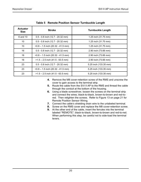
Table 5 Remote Position Sensor Turnbuckle Length<br />
Actuator<br />
Size<br />
Stroke<br />
Turnbuckle Length<br />
6 and 10 0.5 - 0.8 inch (12.7 - 20.32 mm) 1.25 inch (31.75 mm)<br />
10 0.5 - 0.8 inch (12.7 - 20.32 mm) 1.25 inch (31.75 mm)<br />
10 >0.8 – 1.5 inch (20.32 - 41.5 mm) 1.25 inch (31.75 mm)<br />
16 0.5 - 0.8 inch (12.7 - 20.32 mm) 2.90 inch (73.66 mm)<br />
16 >0.8 – 1.5 inch (20.32 - 41.5 mm) 2.90 inch (73.66 mm)<br />
16 >1.5 – 2.5 inch (41.5 - 63.5 mm) 2.90 inch (73.66 mm)<br />
23 0.5 - 0.8 inch (12.7 - 20.32 mm) 5.25 inch (133.35 mm)<br />
23 >0.8 – 1.5 inch (20.32 - 41.5 mm) 5.25 inch (133.35 mm)<br />
23 >1.5 – 2.5 inch (41.5 - 63.5 mm) 5.25 inch (133.35 mm)<br />
4. Remove the M8 cover-retention screw of the RMS and unscrew the<br />
cover to gain access to the terminal strip.<br />
5. Route the cable from the <strong>SVI</strong> <strong>II</strong> AP to the RMS and thread the cable<br />
through the conduit at the bottom of the housing.<br />
6. Using a blade screwdriver, loosen the screws on the terminal strip<br />
and connect the wires; black-to-black, brown-to-brown and red-tored.<br />
Then retighten the screws. Refer to Figure 13 on page 21 for<br />
Remote Position Sensor Wiring.<br />
7. Connect the cable’s shielding drain wire to the unlabeled terminal.<br />
8. Screw on the RMS cover and replace the M8 cover-retention screw.<br />
9. At the other end of the cable, insert the ferrules into the terminal<br />
labeled “REMOTE”; black-to-black, brown-to-brown and red-to-red.<br />
When performing this step, be careful not to side-load the terminal<br />
levers.<br />
20