SVI-II Instruc Man.book - Fagerberg
SVI-II Instruc Man.book - Fagerberg
SVI-II Instruc Man.book - Fagerberg
You also want an ePaper? Increase the reach of your titles
YUMPU automatically turns print PDFs into web optimized ePapers that Google loves.
Masoneilan Dresser<br />
<strong>SVI</strong> <strong>II</strong> AP <strong>Instruc</strong>tion <strong>Man</strong>ual<br />
Note:<br />
Maximum allowable air supply pressure to the <strong>SVI</strong> <strong>II</strong> AP varies<br />
according to actuator and valve size and type. See pressure drop<br />
tables in valve specification sheets to determine correct positioner<br />
supply pressure. Minimum supply pressure should be 5 to 10 psi<br />
(.345 bar - .69 bar) (34.485 - 68.97 kPa) above maximum spring<br />
pressure.<br />
Mounting the<br />
<strong>SVI</strong> <strong>II</strong> AP on<br />
Rotary Valves<br />
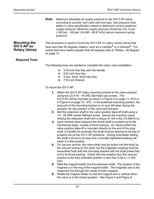
This procedure is used to mount the <strong>SVI</strong> <strong>II</strong> AP on rotary control valves that<br />
have less than 60 degrees rotation, such as a Camflex ® or a Varimax ® . For<br />
valves that have rotation greater than 60 degrees refer to “Rotary - 90 Degree”<br />
on page 13<br />
Required Tools<br />
The following tools are needed to complete the rotary valve installation:<br />
<br />
<br />
<br />
<br />
To mount the <strong>SVI</strong> <strong>II</strong> AP:<br />
3⁄16 inch Hex Key with tee handle<br />
5⁄32 inch Hex Key<br />
3 mm, 4mm, 5mm Hex Key<br />
7⁄16 inch Wrench<br />
1. Attach the <strong>SVI</strong> <strong>II</strong> AP rotary mounting bracket to the valve actuator<br />
using two (2) 5⁄16 - 18 UNC flat-head cap screws. The<br />
<strong>SVI</strong> <strong>II</strong> AP will be mounted as shown in Figure 5 on page 11, ATO or<br />
in Figure 6 on page 12, ATC. In the preferred mounting position, the<br />
long end of the mounting bracket is on your left when facing the<br />
actuator, for any position of the valve and actuator.<br />
2. Bolt the extension shaft to the valve position take-off shaft using a<br />
1⁄4 - 28 UNF socket flathead screw. Secure the machine screw<br />
holding the extension shaft with a torque of 144 in-lbs (16.269 N-m).<br />
3. Upon internal valve pressure the thrust shaft is pushed out to the<br />
mechanical stops, usually a thrust bearing. On valves where the<br />
valve position take-off is mounted directly on the end of the plug<br />
shaft, a Camflex for example, the shaft must be bearing on its stop to<br />
properly set up the <strong>SVI</strong> <strong>II</strong> AP positioner. During hydrostatic testing<br />
the shaft is thrust to its stop and a normally tightened packing will<br />
retain it in that position.<br />
4. On vacuum service, the valve shaft may be drawn into the body by<br />
the vacuum acting on the shaft, but the magnetic coupling must be<br />
assembled flush with the mounting bracket with the shaft pulled fully<br />
out to its thrust bearing. Check that the endplay from the vacuum<br />
position to the fully extended position is less than 0.06 in. (1.524<br />
mm)<br />
5. Slide the magnet holder into the extension shaft. The location of the<br />
magnets is in the ring of the magnet holder. The magnetic axis is the<br />
imaginary line through the center of both magnets.<br />
6. Rotate the magnet holder so that the magnet axis is vertical when<br />
the valve is in the closed position. See Figure 5 and Figure 6.<br />
10


