SVI-II Instruc Man.book - Fagerberg
SVI-II Instruc Man.book - Fagerberg
SVI-II Instruc Man.book - Fagerberg

Create successful ePaper yourself
Turn your PDF publications into a flip-book with our unique Google optimized e-Paper software.
Masoneilan Dresser<br />
<strong>SVI</strong> <strong>II</strong> AP <strong>Instruc</strong>tion <strong>Man</strong>ual<br />
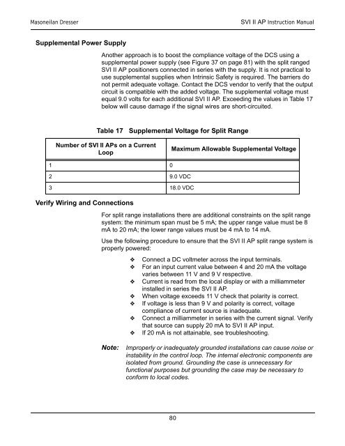
Supplemental Power Supply<br />
Another approach is to boost the compliance voltage of the DCS using a<br />
supplemental power supply (see Figure 37 on page 81) with the split ranged<br />
<strong>SVI</strong> <strong>II</strong> AP positioners connected in series with the supply. It is not practical to<br />
use supplemental supplies when Intrinsic Safety is required. The barriers do<br />
not permit adequate voltage. Contact the DCS vendor to verify that the output<br />
circuit is compatible with the added voltage. The supplemental voltage must<br />
equal 9.0 volts for each additional <strong>SVI</strong> <strong>II</strong> AP. Exceeding the values in Table 17<br />
below will cause damage if the signal wires are short-circuited.<br />
Table 17 Supplemental Voltage for Split Range<br />
Number of <strong>SVI</strong> <strong>II</strong> APs on a Current<br />
Loop<br />
Maximum Allowable Supplemental Voltage<br />
1 0<br />
2 9.0 VDC<br />
3 18.0 VDC<br />
Verify Wiring and Connections<br />
For split range installations there are additional constraints on the split range<br />
system: the minimum span must be 5 mA; the upper range value must be 8<br />
mA to 20 mA; the lower range values must be 4 mA to 14 mA.<br />
Use the following procedure to ensure that the <strong>SVI</strong> <strong>II</strong> AP split range system is<br />
properly powered:<br />
<br />
<br />
<br />
<br />
<br />
<br />
<br />
Connect a DC voltmeter across the input terminals.<br />
For an input current value between 4 and 20 mA the voltage<br />
varies between 11 V and 9 V respective.<br />
Current is read from the local display or with a milliammeter<br />
installed in series the <strong>SVI</strong> <strong>II</strong> AP.<br />
When voltage exceeds 11 V check that polarity is correct.<br />
If voltage is less than 9 V and polarity is correct, voltage<br />
compliance of current source is inadequate.<br />
Connect a milliammeter in series with the current signal. Verify<br />
that source can supply 20 mA to <strong>SVI</strong> <strong>II</strong> AP input.<br />
If 20 mA is not attainable, see troubleshooting.<br />
Note:<br />
Improperly or inadequately grounded installations can cause noise or<br />
instability in the control loop. The internal electronic components are<br />
isolated from ground. Grounding the case is unnecessary for<br />
functional purposes but grounding the case may be necessary to<br />
conform to local codes.<br />
80