

Hydraulic Design of Highway Culverts - DOT On-Line Publications
Hydraulic Design of Highway Culverts - DOT On-Line Publications
Hydraulic Design of Highway Culverts - DOT On-Line Publications

Create successful ePaper yourself
Turn your PDF publications into a flip-book with our unique Google optimized e-Paper software.
3. Headwater. Energy is required to force flow through a culvert. This energy takes the form <strong>of</strong><br />
an increased water surface elevation on the upstream side <strong>of</strong> the culvert. The depth <strong>of</strong> the<br />
upstream water surface measured from the invert at the culvert entrance is generally referred to<br />
as headwater depth (Figures I-13 and I-14).<br />
A considerable volume <strong>of</strong> water may be ponded upstream <strong>of</strong> a culvert installation under high fills<br />
or in areas with flat ground slopes. The pond which is created may attenuate flood peaks under<br />
such conditions. This peak discharge attenuation may justify a reduction in the required culvert<br />
size.<br />
4. Tailwater. Tailwater is defined as the depth <strong>of</strong> water downstream <strong>of</strong> the culvert measured<br />
from the outlet invert. Figure I-14 It is an important factor in determining culvert capacity under<br />
outlet control conditions. Tailwater may be caused by an obstruction in the downstream channel<br />
or by the hydraulic resistance <strong>of</strong> the channel. In either case, backwater calculations from the<br />
downstream control point are required to precisely define tailwater. When appropriate, normal<br />
depth approximations may be used instead <strong>of</strong> backwater calculations.<br />
5. Outlet Velocity. Since a culvert usually constricts the available channel area, flow velocities<br />
in the culvert are likely to be higher than in the channel. These increased velocities can cause<br />
streambed scour and bank erosion in the vicinity <strong>of</strong> the culvert outlet. Minor problems can<br />
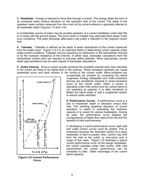
Figure I-15--Culvert Performance<br />
Curve<br />
occasionally be avoided by increasing the barrel<br />
roughness. Energy dissipaters and outlet protection<br />
devices are sometimes required to avoid excessive<br />
scour at the culvert outlet. When a culvert is<br />
operating under inlet control and the culvert barrel is<br />
not operating at capacity, it is <strong>of</strong>ten beneficial to<br />
flatten the barrel slope or add a roughened section<br />
to reduce outlet velocities.<br />
6. Performance Curves. A performance curve is a<br />
plot <strong>of</strong> headwater depth or elevation versus flow<br />
rate. The resulting graphical depiction <strong>of</strong> culvert<br />
operation is useful in evaluating the hydraulic<br />
capacity <strong>of</strong> a culvert for various headwaters. Among<br />
its uses, the performance curve displays the<br />
consequences <strong>of</strong> higher flow rates at the site and the<br />
benefits <strong>of</strong> inlet improvements.<br />
In developing a culvert performance curve, both inlet<br />
and outlet control curves must be plotted. This is<br />
necessary because the dominant control at a given<br />
headwater is hard to predict. Also, control may shift<br />
from the inlet to the outlet, or vice-versa over a<br />
range <strong>of</strong> flow rates. Figure I-15 illustrates a typical<br />
culvert performance curve. At the design headwater,<br />
the culvert operates under inlet control. With inlet<br />
improvement the culvert performance can be<br />
increased to take better advantage <strong>of</strong> the culvert<br />
barrel capacity.<br />
9


