10 - H1 - Desy
10 - H1 - Desy
10 - H1 - Desy

Create successful ePaper yourself
Turn your PDF publications into a flip-book with our unique Google optimized e-Paper software.
<strong>10</strong>0 Cross section building<br />
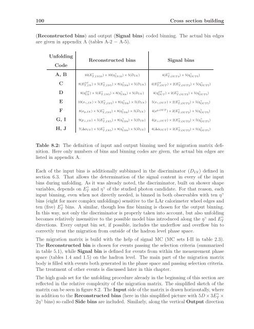
(Reconstructed bins) and output (Signal bins) coded binning. The actual bin edges<br />
are given in appendix A (tables A-2 − A-5).<br />
Unfolding<br />
Code<br />
Reconstructed bins<br />
Signal bins<br />
A, B <strong>10</strong>(E γ T,IN<strong>10</strong> ) × <strong>10</strong>(ηγ IN<strong>10</strong> ) × 5(D IN) 4(E γ T,OUT4 ) × 5(ηγ OUT5 )<br />
C<br />
D<br />
8(E jet<br />
T,IN ) × 5(Eγ T,IN5 ) × 8(ηγ IN8 ) × 5(D IN)<br />
8(η jet<br />
IN ) × 5(Eγ T,IN5 ) × 8(ηγ IN8 ) × 5(D IN)<br />
4(E jet<br />
T,OUT ) × 2(Eγ T,OUT2 ) × 5(ηγ OUT5 )<br />
4(η jet<br />
OUT ) × 2(Eγ T,OUT2 ) × 5(ηγ OUT5 )<br />
E <strong>10</strong>(x γ,IN ) × 5(E γ T,IN5 ) × 8(ηγ IN8 ) × 5(D IN) 5(x γ,OUT ) × 2(E γ T,OUT2 ) × 5(ηγ OUT5 )<br />
F 8(x p,IN ) × 5(E γ T,IN5 ) × 8(ηγ IN8 ) × 5(D IN) 4(x p,OUT ) × 2(E γ T,OUT2 ) × 5(ηγ OUT5 )<br />
G, I 9(p ⊥,IN ) × 5(E γ T,IN5 ) × 8(ηγ IN8 ) × 5(D IN) 4(p ⊥,OUT ) × 2(E γ T,OUT2 ) × 5(ηγ OUT5 )<br />
H, J 7(∆φ IN ) × 5(E γ T,IN5 ) × 8(ηγ IN8 ) × 5(D IN) 4(∆φ OUT ) × 2(E γ T,OUT2 ) × 5(ηγ OUT5 )<br />
Table 8.2: The definition of input and output binning used for migration matrix definition.<br />
Here only numbers of bins and binning codes are given, the actual bin edges are<br />
listed in appendix A.<br />
Each of the input bins is additionally subbinned in the discriminator (D IN ) defined in<br />
section 6.3. That allows the determination of the signal content in every of the input<br />
bins during unfolding. As it was already noted, the discriminator, built on shower shape<br />
variables, depends on E γ T and ηγ of the studied photon candidate. For that reason, each<br />
input binning, even when not directly needed, is binned in both observables with ten η γ<br />
bins (eight for more complex unfoldings) sensitive to the LAr calorimeter wheel edges and<br />
ten (five) E γ T<br />
bins. A similar, though less fine binning is chosen for the output binning.<br />
In this way, not only the discriminator is properly taken into account, but also unfolding<br />
becomes relatively insensitive to the possible model bias introduced along the η γ and E γ T<br />
directions. Every output bin set, if possible, includes the underflow and overflow bin to<br />
correctly treat the migration from outside of the hadron level phase space.<br />
The migration matrix is build with the help of signal MC (MC sets I-II in table 2.3).<br />
The Reconstructed bin is chosen for events passing the selection criteria (summarized<br />
in table 5.1), while Signal bin is defined for events from within the measurement phase<br />
space (tables 1.4 and 1.5) on the hadron level. The main part of the migration matrix<br />
body is filled with events both generated in the phase space and passing selection criteria.<br />
The treatment of other events is discussed later in this chapter.<br />
The high goals set for the unfolding procedure already in the beginning of this section are<br />
reflected in the relative complexity of the migration matrix. The simplified sketch of the<br />
matrix can be seen in figure 8.2. The Input side of the matrix is drawn horizontally, where<br />
in addition to the Reconstructed bins (here in this simplified picture with 5D ×3E γ T ×<br />
2η γ bins) so called Side bins are included. Similarly, along the vertical Output direction