

CME34M Hardware Manual - RTD Embedded Technologies, Inc.
CME34M Hardware Manual - RTD Embedded Technologies, Inc.
CME34M Hardware Manual - RTD Embedded Technologies, Inc.

You also want an ePaper? Increase the reach of your titles
YUMPU automatically turns print PDFs into web optimized ePapers that Google loves.
Utility Port Connector (CN5)<br />
The utility port connector implements the following functions:<br />
• PC/AT compatible keyboard port<br />
• PS/2 mouse port<br />
• Speaker port (0.1W output)<br />
• <strong>Hardware</strong> Reset input<br />
• Soft Power Button input<br />
• Battery input for Real Time Clock<br />
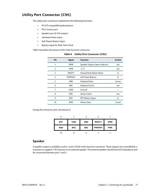
Table 8 provides the pinout of the multi-function connector.<br />
Table 8<br />
Utility Port Connector (CN5)<br />
Pin Signal Function In/Out<br />
1 SPKR Speaker Output (open collector) out<br />
2 PWR +5 V out<br />
3 RESET# <strong>Manual</strong> Push-Button Reset in<br />
4 PWRSW# Soft Power Button in<br />
5 KBD Keyboard Data in/out<br />
6 KBC Keyboard Clock out<br />
7 GND Ground —<br />
8 MSC Mouse Clock out<br />
9 BAT RTC Battery Input in<br />
10 MSD Mouse Data in/out<br />
Facing the connector pins, the pinout is:<br />
9 7 5 3 1<br />
BAT GND KBD RESET# SPKR<br />
MSD MSC KBC PWRSW# PWR<br />
10 8 6 4 2<br />
Speaker<br />
A speaker output is available on pins 1 and 2 of the multi-function connector. These outputs are controlled by a<br />
transistor to supply 0.1 W of power to an external speaker. The external speaker should have 8 Ω impedance and<br />
be connected between pins 1 and 2.<br />
BDM-610000076 Rev A Chapter 3: Connecting the cpuModule 27


